Last updated: 2026.7.14
| Contents of this page |
Goal for this time
 |
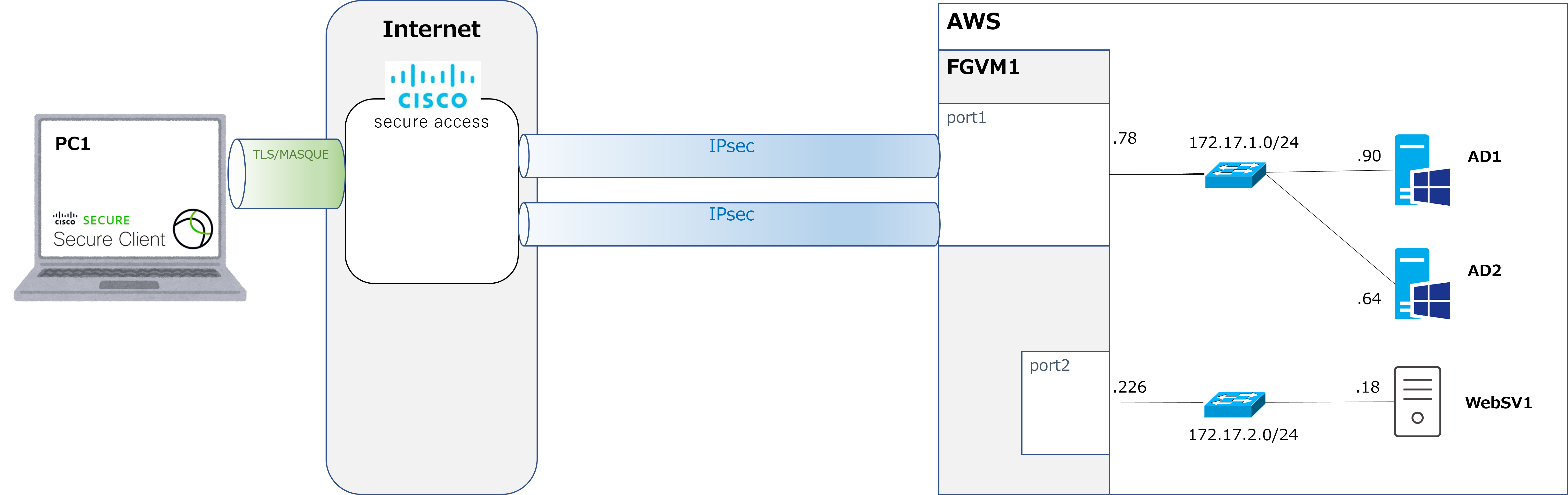
Now, last time we set up SCIM to sync the user database between Cisco Secure Access and Entra ID. From here on, we're going to try out several different scenarios. I'll go into more detail next time, but the goal for scenario 1 is, as shown in the diagram above, to get a remote worker's PC1 connecting to Secure Access over remote-access VPN and accessing a server inside AWS. |
 |
You say that so casually, but doesn't it sound incredibly difficult? Still, it does feel like cutting-edge technology, which is exciting. |
|
That's right. To get there, we first need to connect Secure Access and AWS via IPsec. That's what we'll look at this time. |
IPsec connection settings on the Secure Access side
|
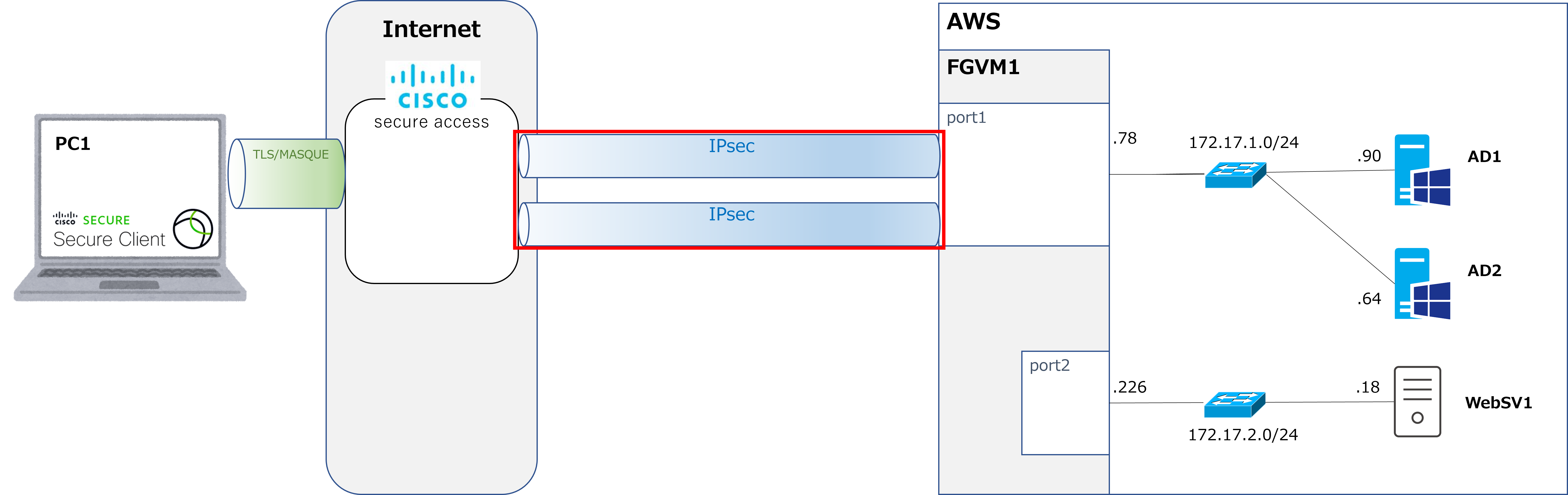
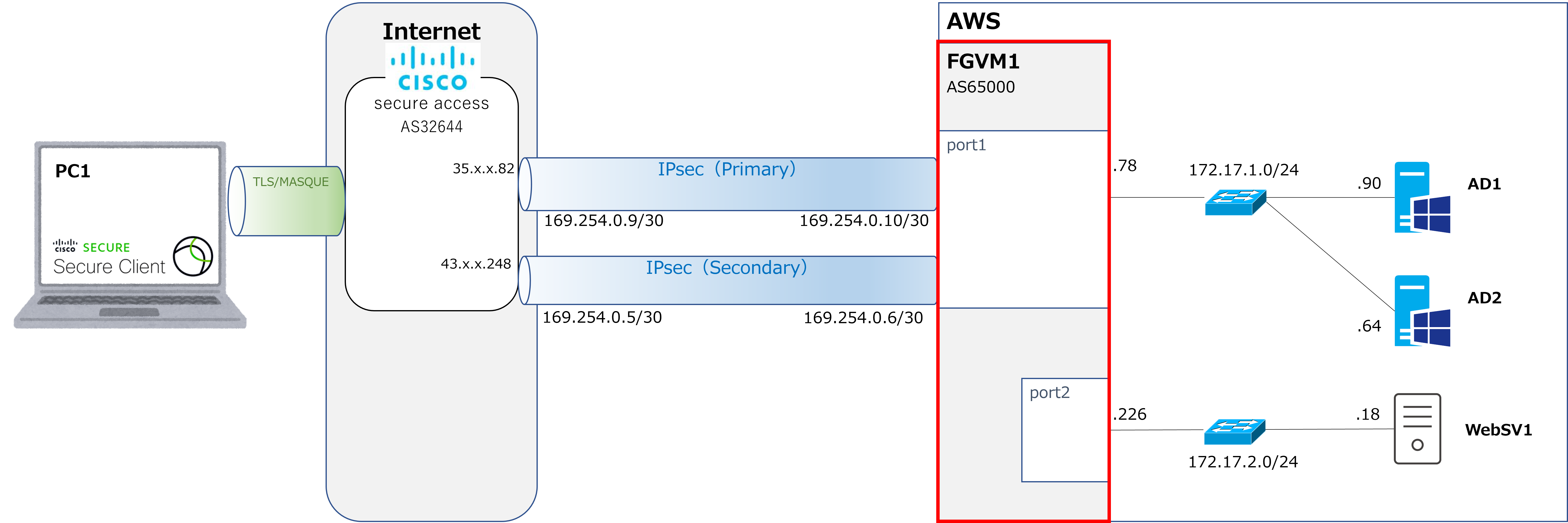
The FGVM and servers inside AWS are already built, so we'll start from the IPsec connection shown in the red box. First, let's configure the IPsec connection on the Secure Access side. |
|
Hmm, it looks like two IPsec tunnels are being set up — is that for redundancy? |
|
Yes, that's right. Now let's go through the Secure Access dashboard. |
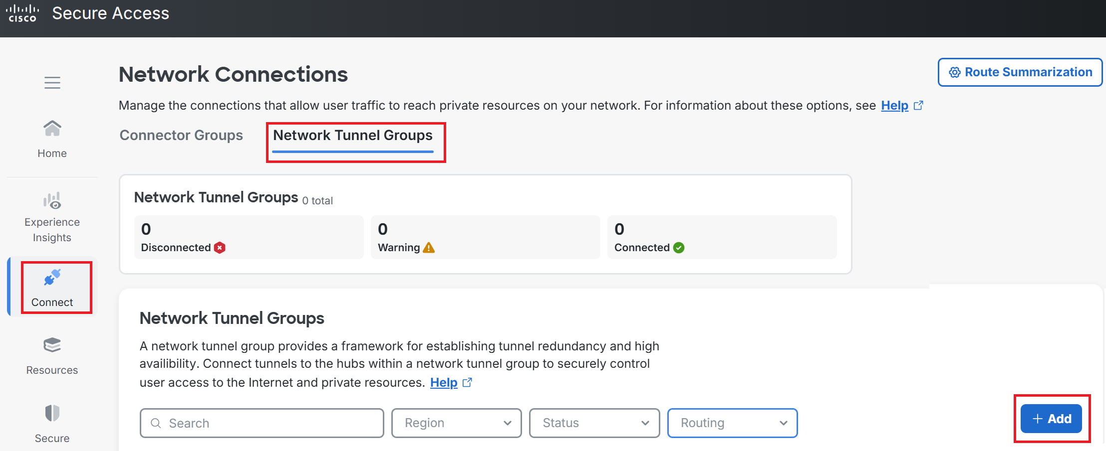
① Go to Connect → Network Connections → Network Tunnel Groups → +Add.
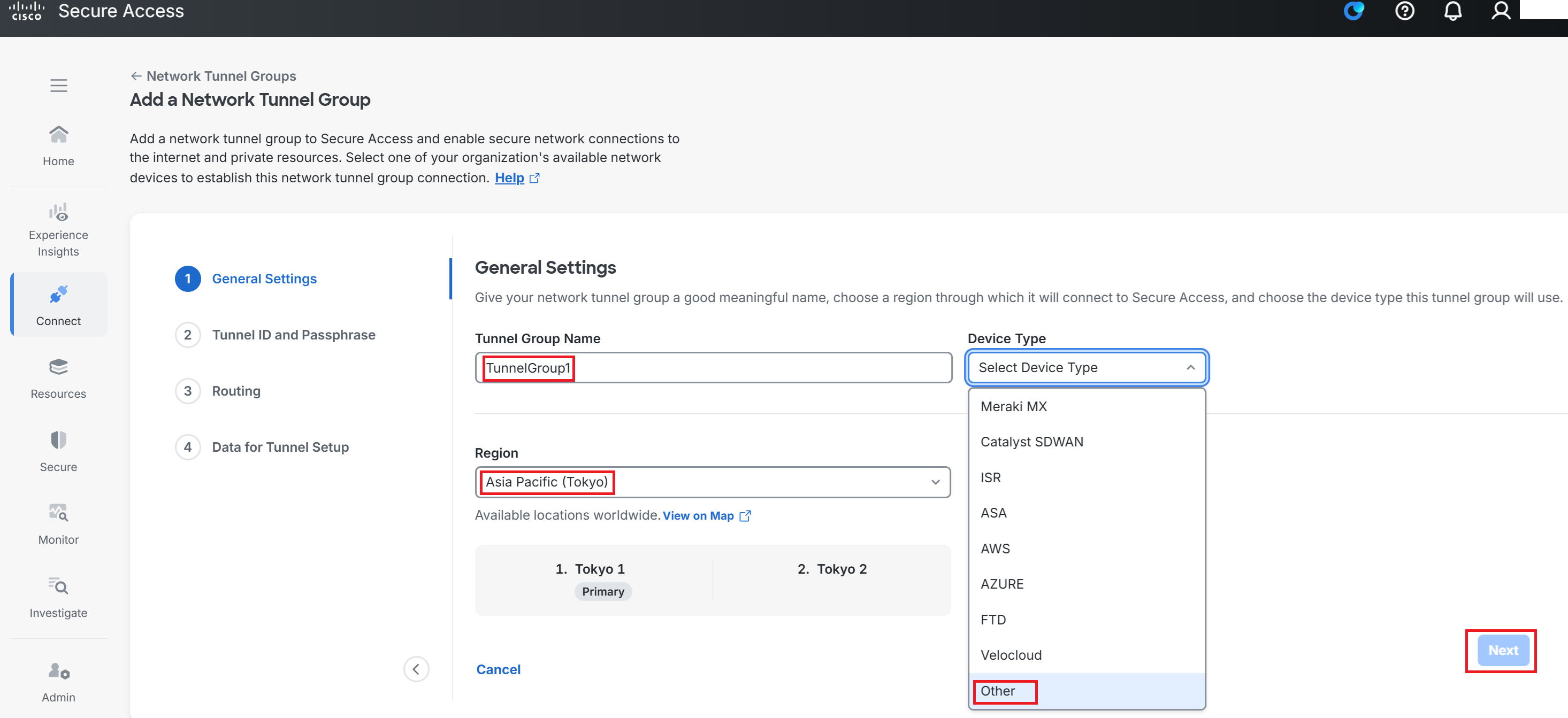
② Enter any Tunnel Group Name you like. This time we used TunnelGroup1. (I tend to be the type who just names things literally.)
For Region, you'd normally pick whichever is nearest. This time we selected Asia Pacific (Tokyo).
For Device Type, since we're connecting to a Fortigate VM this time, select Other. Then click Next.
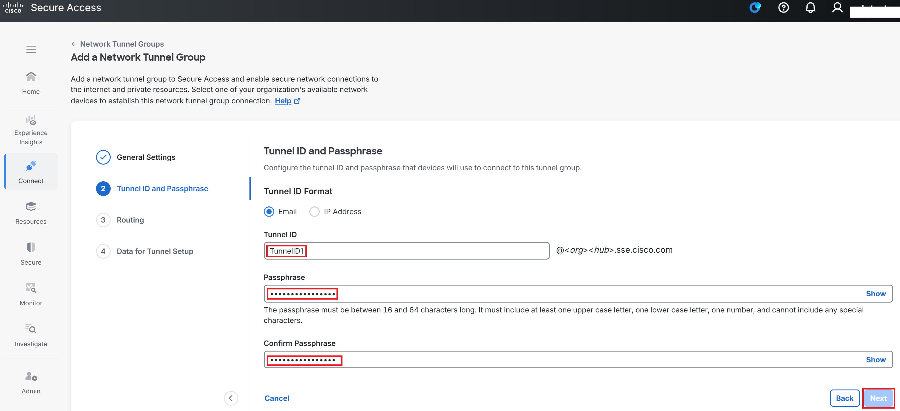
③ Enter any Tunnel ID and Passphrase you like, then click Next. We used TunnelID1 for the Tunnel ID.
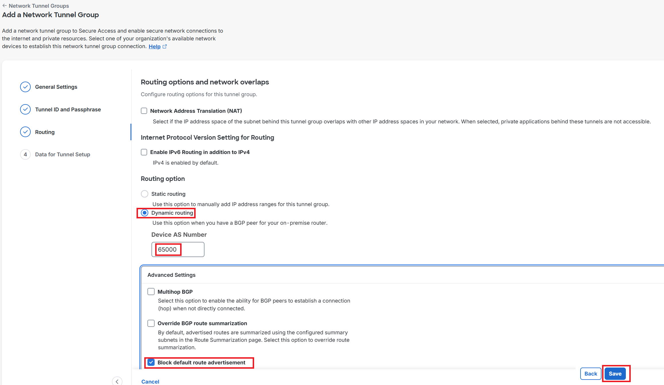
④ For the Routing option, since we're using BGP this time, check Dynamic routing and enter the FortiVM's AS number (65000 in this case).
Under Advanced Settings, check Block default route advertisement and click Save.
Note that by default, Secure Access advertises a default route to FortiVM over BGP, but checking this box stops that advertisement from happening.
*If you want the default route to be advertised, leave this unchecked.
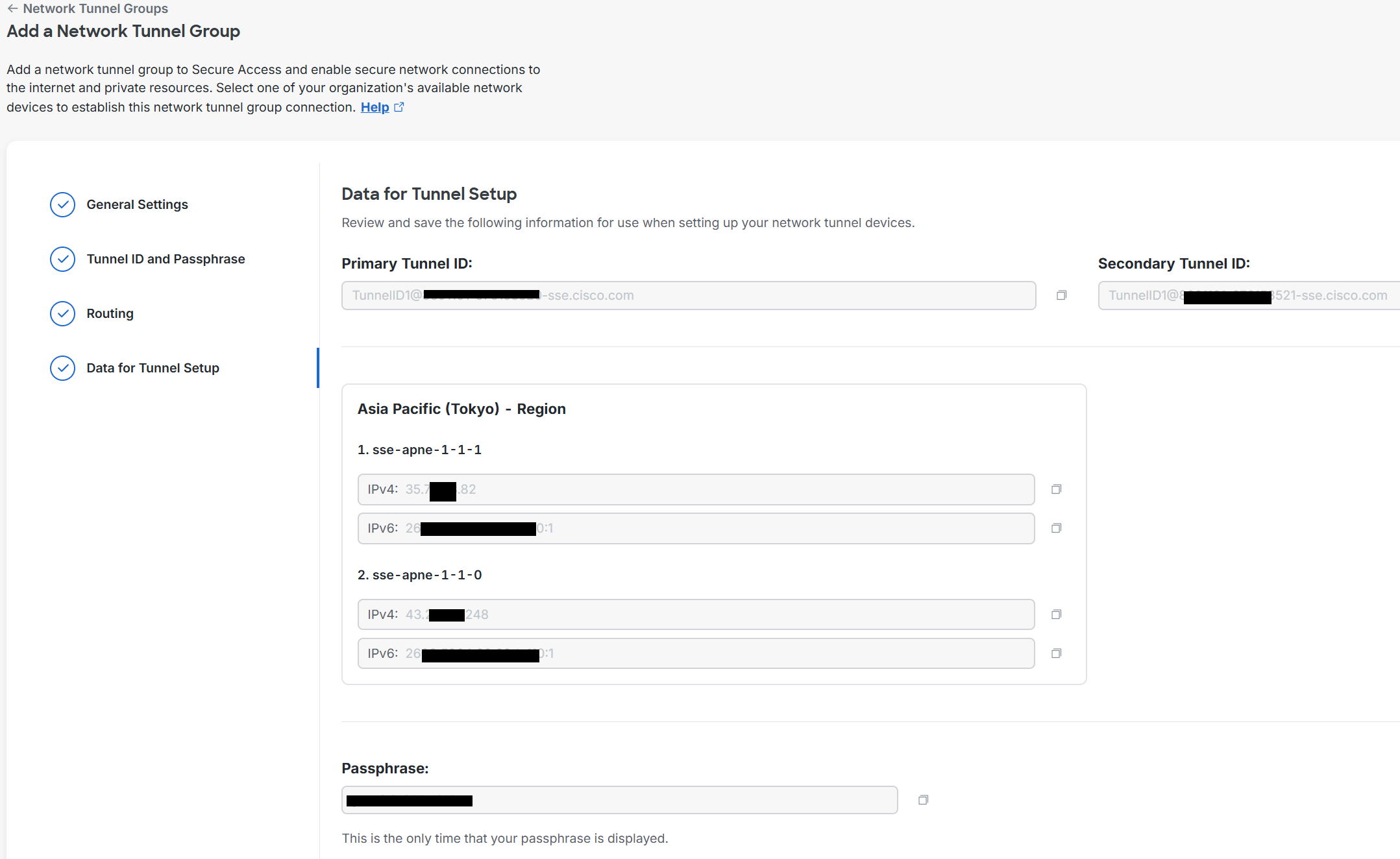
⑤ After completing the steps so far, two listening IP addresses for the IPsec connection are issued on the Secure Access side — one for the primary tunnel, and one for the secondary tunnel.
The Primary Tunnel ID and Secondary Tunnel ID are needed later when configuring IPsec on the FortiVM side.
You don't have to write these down by hand — there's a CSV download button at the top right of the screen, which lets you get a CSV file containing this information.
Then click Done at the bottom right of the screen.
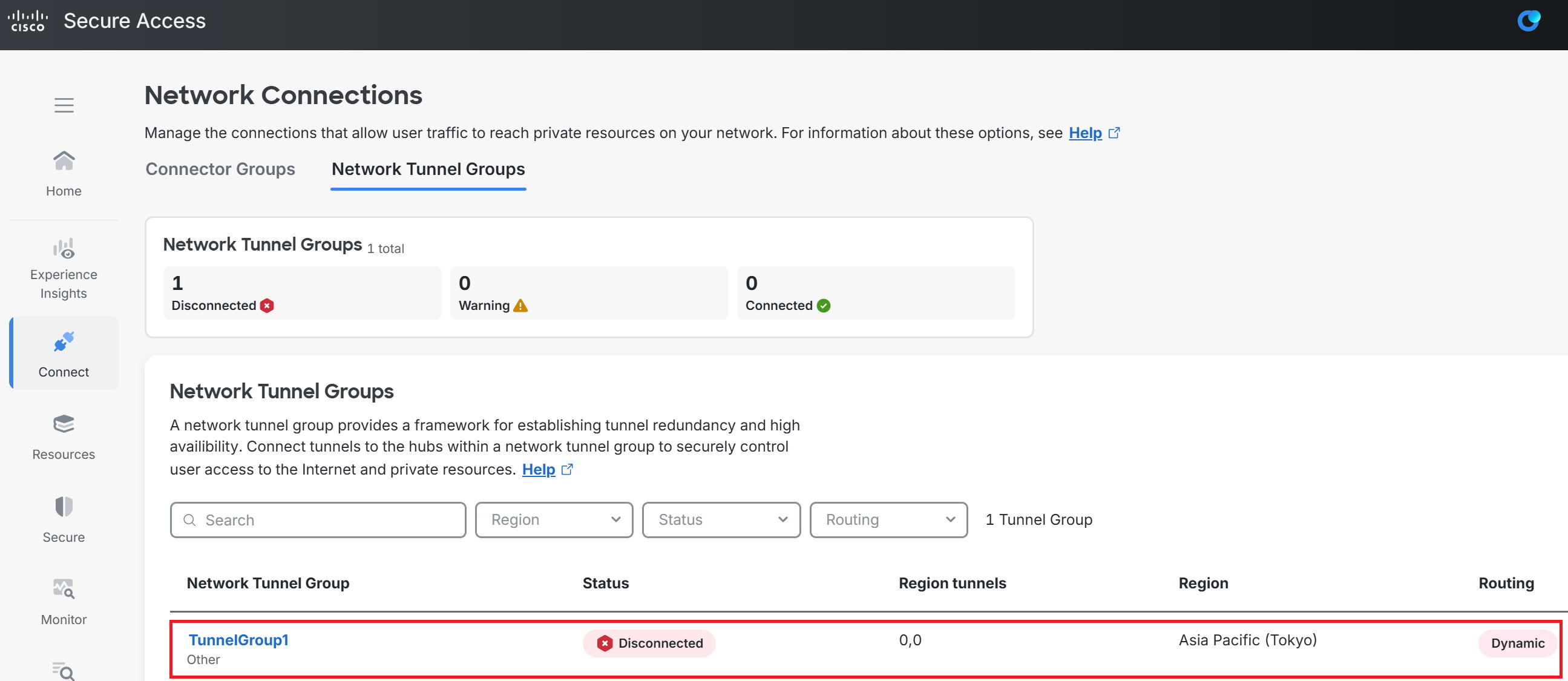
⑥ Back on the original screen, the tunnel we just created is now listed. Since the IPsec connection hasn't been established yet, it shows as Disconnected.
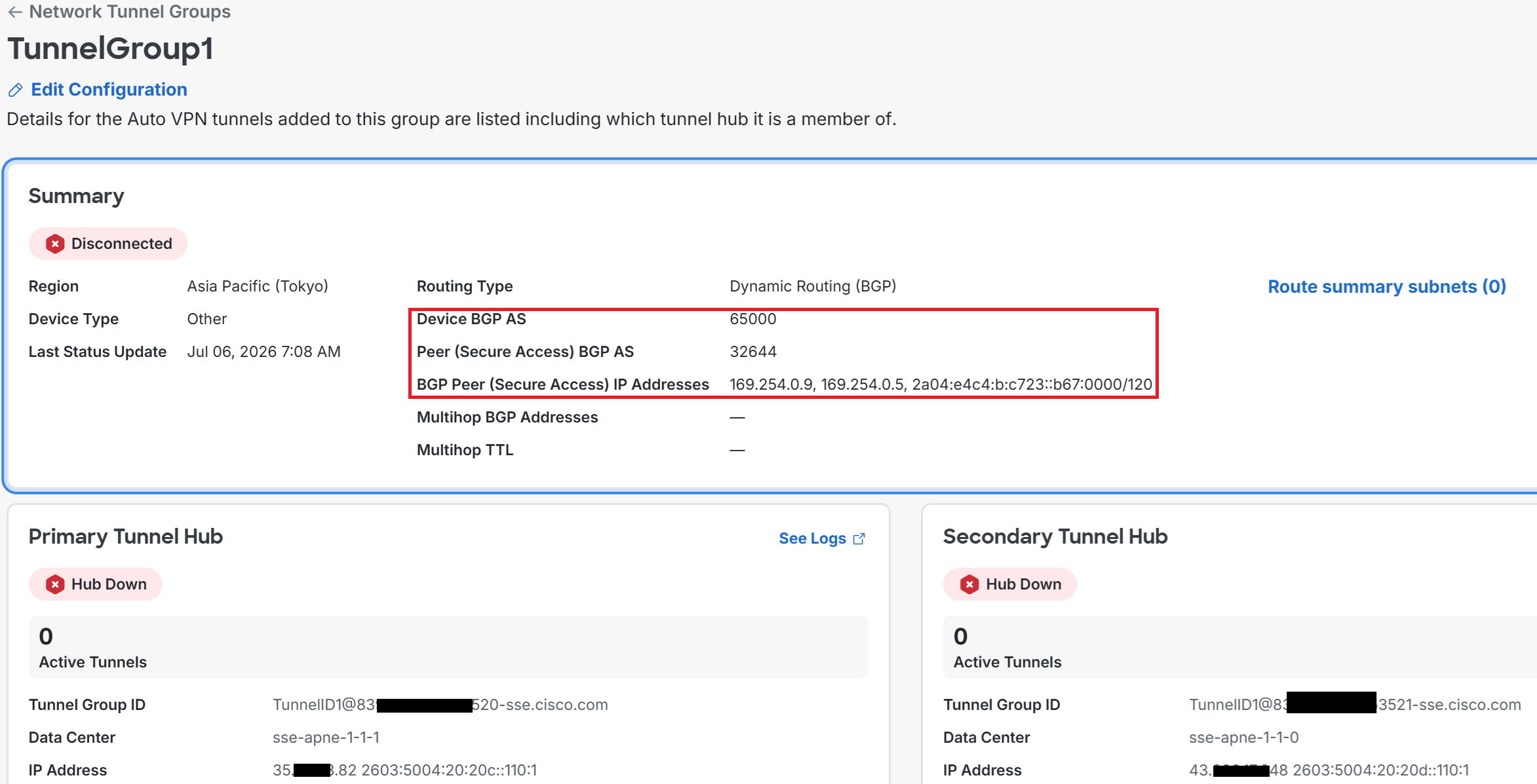
Click into TunnelGroup1 in the red box.
⑦ As shown on the second line in the red box, the AS number on the Secure Access side is 32644. This number is fixed.
The IP addresses of the IPsec tunnel interfaces on the Secure Access side are 169.254.0.9 for Primary and 169.254.0.5 for Secondary. These are also fixed.
That means the IPsec tunnel interface IP addresses on the FortiVM side must correspondingly be 169.254.0.10/30 and 169.254.0.6/30.
Settings on the FortiVM side
|
Next, let's configure IPsec, BGP, and firewall policy on the FortiVM side. |
| IPsec configuration *For localid, enter the Primary Tunnel ID and Secondary Tunnel ID issued on the Secure Access side. |
| config vpn ipsec phase1-interface edit To_CSA_primary set interface port1 set ike-version 2 set peertype any set net-device disable set proposal aes256-sha256 set remote-gw 35.xx.xx.82 set psksecret xxxxxx set localid TunnelID1@839xxxx-xxxx73703-sse.cisco.com next edit To_CSA_secondary set interface port1 set ike-version 2 set peertype any set net-device disable set proposal aes256-sha256 set remote-gw 43.xx.xx.248 set psksecret xxxxxx set localid TunnelID1@839xxxx-xxxx73705-sse.cisco.com next end config vpn ipsec phase2-interface edit To_CSA_primary_ph2 set phase1name To_CSA_primary set proposal aes256-sha256 set auto-negotiate enable next edit To_CSA_secondary_ph2 set phase1name To_CSA_secondary set proposal aes256-sha256 set auto-negotiate enable next end config system int edit To_CSA_primary set ip 169.254.0.10/32 set remote-ip 169.254.0.9/30 next edit To_CSA_secondary set ip 169.254.0.6/32 set remote-ip 169.254.0.5/30 next end |
| BGP configuration |
| config router bgp set as 65000 set router-id 172.17.1.78 config neighbor edit 169.254.0.9 set remote-as 32644 next edit 169.254.0.5 set remote-as 32644 next end config network edit 1 set prefix 172.17.1.0/24 next edit 2 set prefix 172.17.2.0/24 next end end |
| FW policy configuration |
| config firewall policy edit 110 set name CSA_>_AWS set srcintf To_CSA_primary To_CSA_secondary set dstintf port1 port2 set action accept set srcaddr all set dstaddr 10.0.0.0/8 172.16.0.0/12 192.168.0.0/16 set schedule always set service ALL set logtraffic all next end |
*Anything shown in bold can be named whatever you like.
Verification > Checking on the FortiVM side
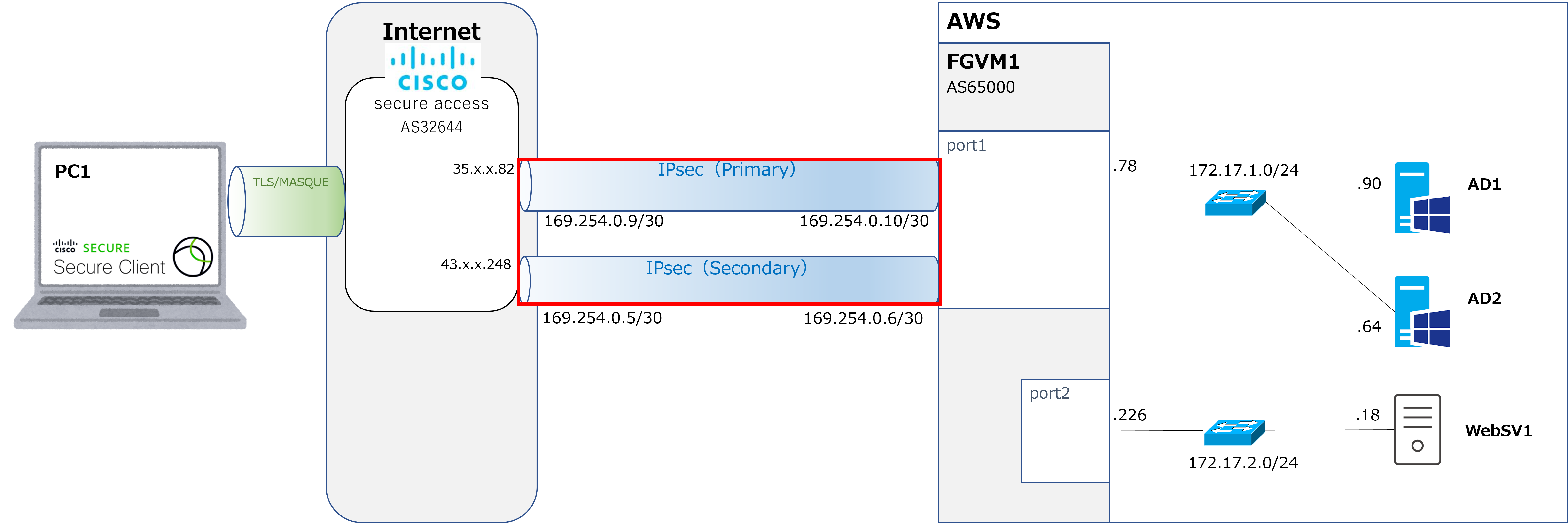
| Checking IPsec tunnel status |
| FGVM1 # get vpn ipsec tunnel summary 'To_CSA_primary' 35.x.x.82:4500 selectors(total,up): 1/1 rx(pkt,err): 17/0 tx(pkt,err): 18/3 transit-gateway: disable 'To_CSA_secondary' 43.x.x.248:4500 selectors(total,up): 1/1 rx(pkt,err): 17/0 tx(pkt,err): 19/3 transit-gateway: disable *1/1 indicates that the IPsec tunnel is up. |
| Pinging the IPsec tunnel interface on the Secure Access side |
| FGVM1 # execute ping 169.254.0.9 PING 169.254.0.9 (169.254.0.9): 56 data bytes 64 bytes from 169.254.0.9: icmp_seq=0 ttl=64 time=1.1 ms 64 bytes from 169.254.0.9: icmp_seq=1 ttl=64 time=1.1 ms FGVM1 # execute ping 169.254.0.5 PING 169.254.0.5 (169.254.0.5): 56 data bytes 64 bytes from 169.254.0.5: icmp_seq=0 ttl=64 time=1.5 ms 64 bytes from 169.254.0.5: icmp_seq=1 ttl=64 time=1.5 ms |
|
Great, the tunnel is up and the pings are working too! |
|
Right. Next, let's check the BGP side of things. |
| Checking BGP neighbors |
| FGVM1 # get router info bgp nei 169.254.0.9 VRF 0 neighbor table: BGP neighbor is 169.254.0.9, remote AS 32644, local AS 65000, external link BGP version 4, remote router ID 169.254.0.1 BGP state = Established, up for 00:02:19 (remainder omitted) FGVM1 # get router info bgp nei 169.254.0.5 VRF 0 neighbor table: BGP neighbor is 169.254.0.5, remote AS 32644, local AS 65000, external link BGP version 4, remote router ID 169.254.0.1 BGP state = Established, up for 00:02:21 |
|
Since it shows "Established," that means BGP is up with no issues. |
|
That's right. Next, let's check the Secure Access side. |
Verification > Checking on the Secure Access side
① Go to Connect → Network Connections → Network Tunnel Groups, and you'll see Connected showing as 1.
Click on TunnelGroup1 below it.
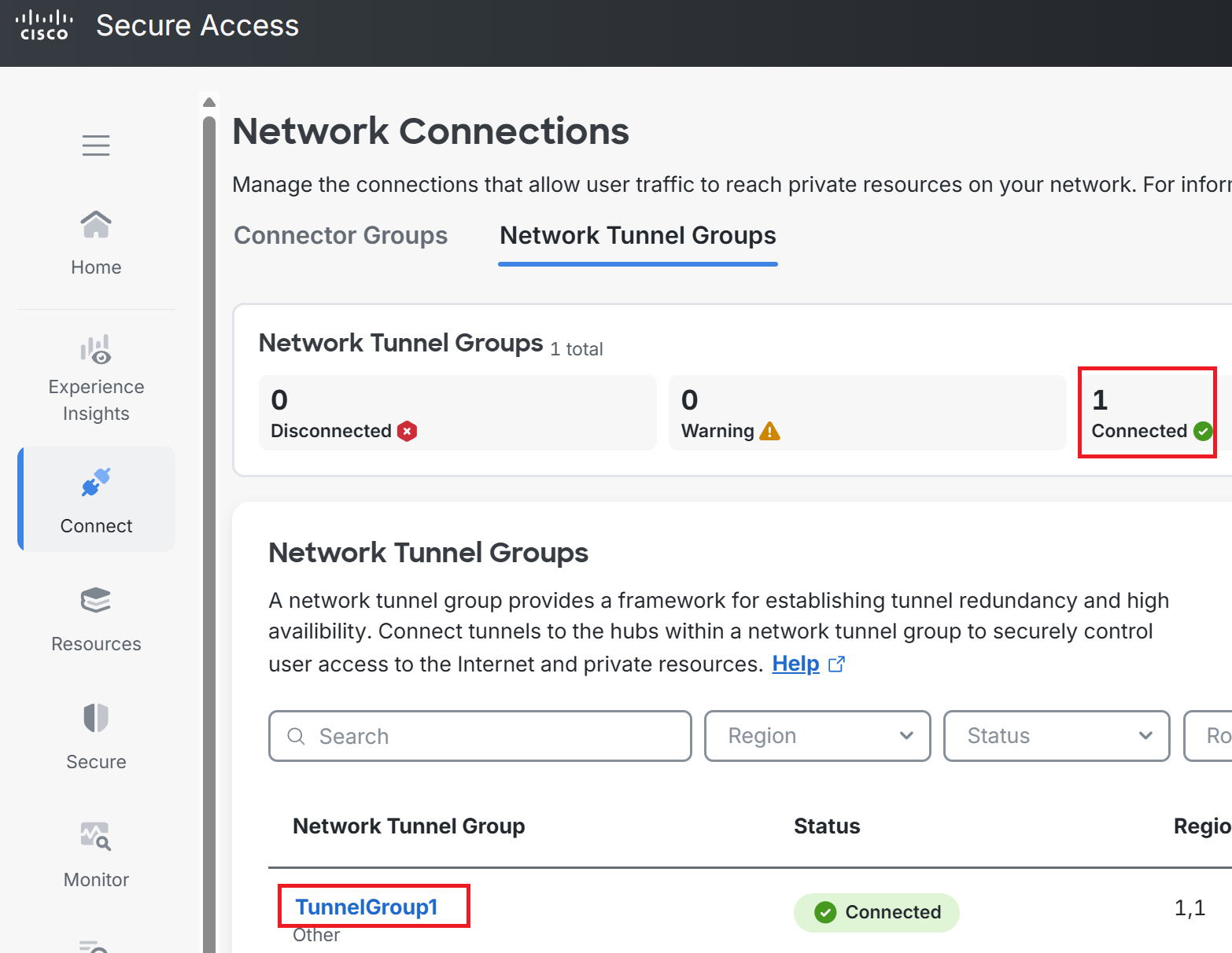
② Both the Primary and Secondary Tunnel Hubs are showing as Up.
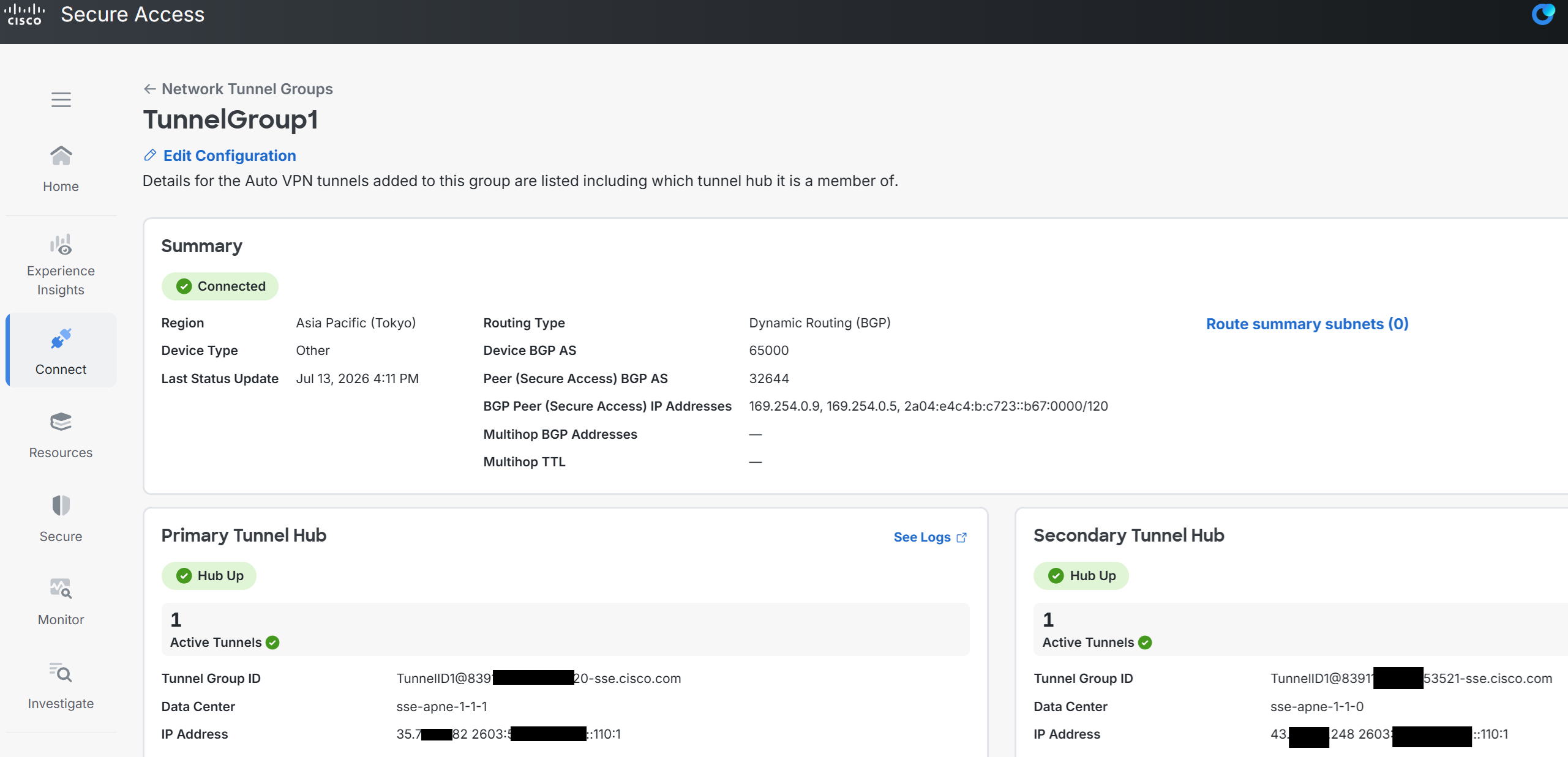
③ Scrolling down from the screen in step ② above shows the following. Click Primary 1.

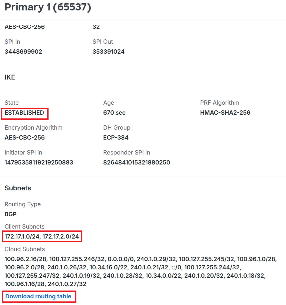
④ The detailed screen below is displayed. The IKE State shows ESTABLISHED.
Under BGP, in the Client subnets section, you can see the two network addresses
(172.17.1.0/24 and 172.17.2.0/24) that FortiVM is advertising to Secure Access.
Clicking Download routing table below that lets you download the routing table. (Details omitted here.)
|
So that confirms the routes advertised by FortiVM are being received properly. |
|
That's right. Next time, we'll look at configuring remote access. |