Last updated: 2026.9.6
| Contents of this page |
Goal for this time
 |
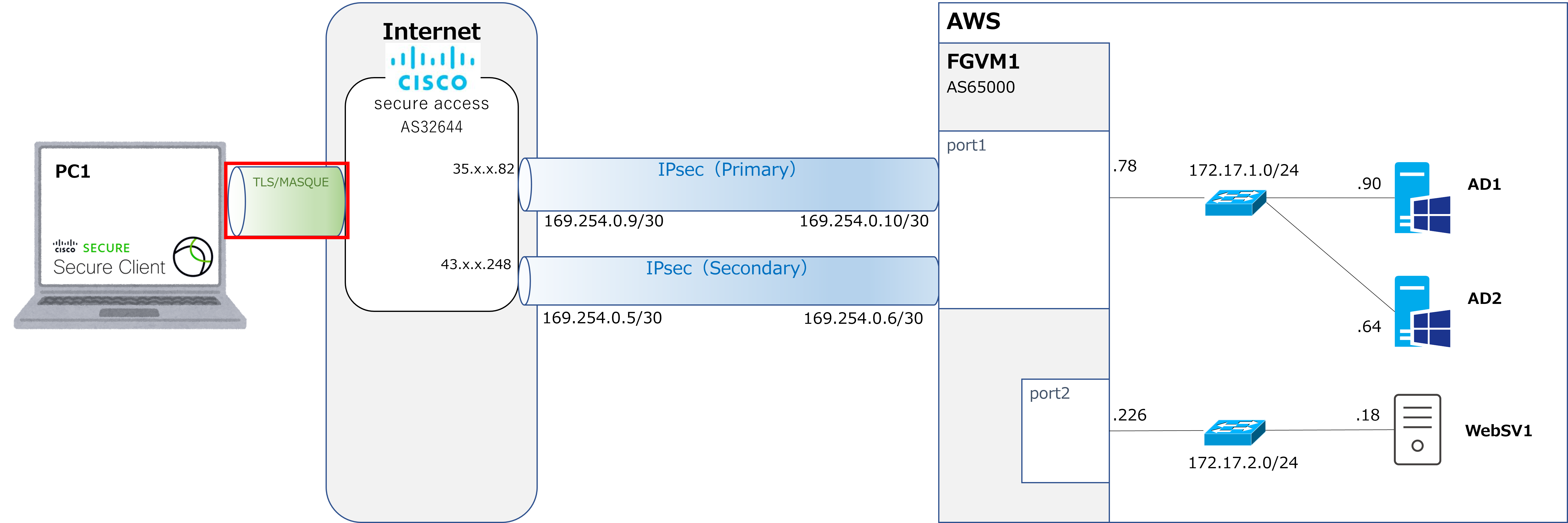
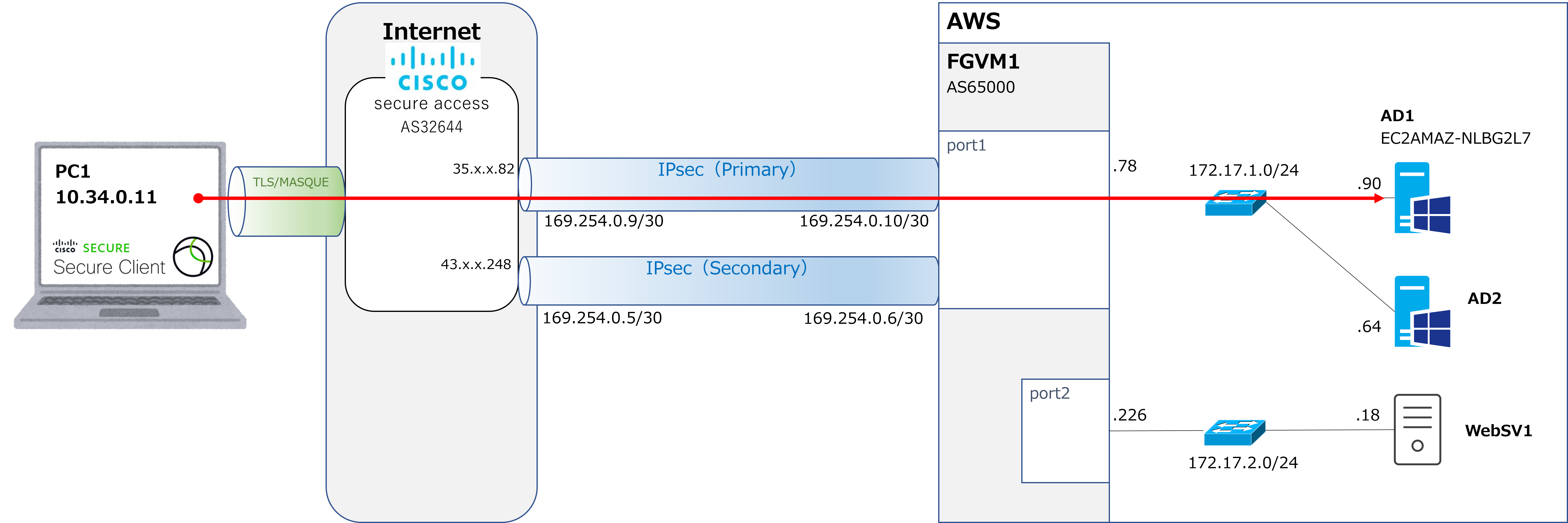
Last time, we configured the IPsec connection between Cisco Secure Access and the FGVM. This time, I'd like to look at the VPN connection setup shown in the red box in the diagram above. Note that this time, PC1 is making a VPN connection to Secure Access, which is a cloud service. Because it's a VPN connection service provided as a cloud service, it's called VPNaaS (VPN as a Service). |
 |
I see. So once this is connected, PC1 will finally be able to access the servers within AWS. |
|
That's right. |
Configuring the IP pool issued to remote access endpoints
|
First, we'll configure the IP pool that gets issued to remote access endpoints. This time, we'll use 10.34.0.0 through 10.34.0.239 as the IPs issued to client endpoints. We'll also provide 10.34.0.240 through 10.34.0.255 (10.34.0.240/28) as the IPs that Cisco reserves for system use. |
①Go to Connect → End User Connectivity → Manage.

②Go to Add IP Pool.

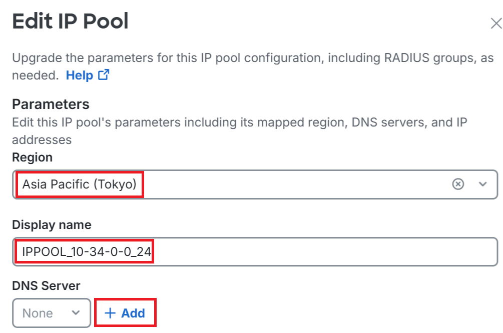
③This time I selected Asia Pacific (Tokyo) for Region.
Enter any name you like for Displayname. This time I used IPPOOL_10-34-0-0_24. Click Add under DNS Server.
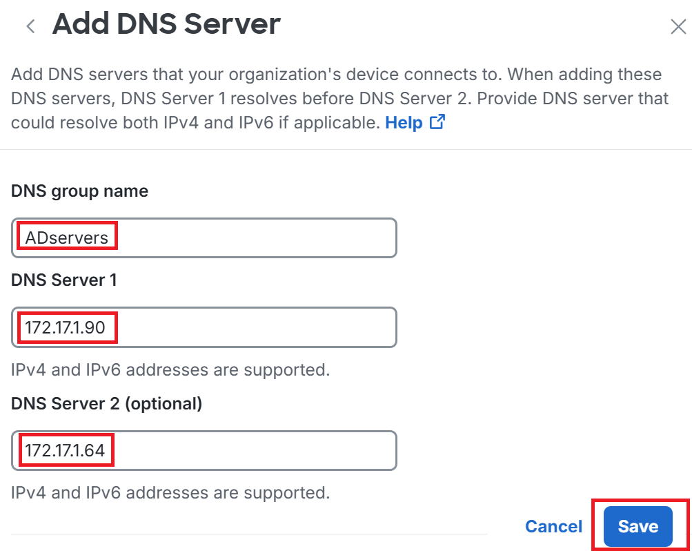
④A new DNS configuration screen appears.
Enter any name you like for DNS group name. This time I used ADservers, since the AD server acts as the internal DNS server.
Enter the AD server's address for DNS Server1 and Server2, then click Save.
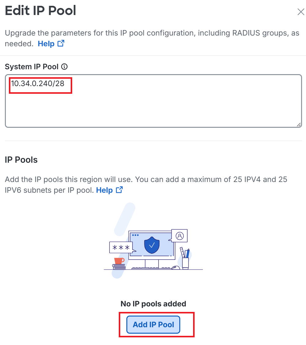
⑤Back on the original screen, enter the System IP Pool. The System IP Pool is not an address issued to client endpoints.
Apparently it's the address Secure Access itself uses as the source IP when, for example, accessing an internal RADIUS server.
This time I entered 10.34.0.240/28 for the System IP Pool.
Then click Add IP Pool near the bottom of the screen.
⑥An Add IP Pool screen opens.
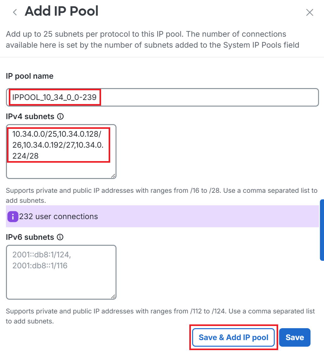
Enter any name you like for IP pool name. This time I used IPPOOL_10_34_0_0-239, since we're planning to issue 10.34.0.0 through 10.34.0.239 to client endpoints.
For IPv4 subnets, enter five subnets so that 10.34.0.0 through 10.34.0.239 is fully covered.
Then click Save & Add IP pool near the bottom.
*If clicking it doesn't return you to the original screen, close it with the "×" at the top right.
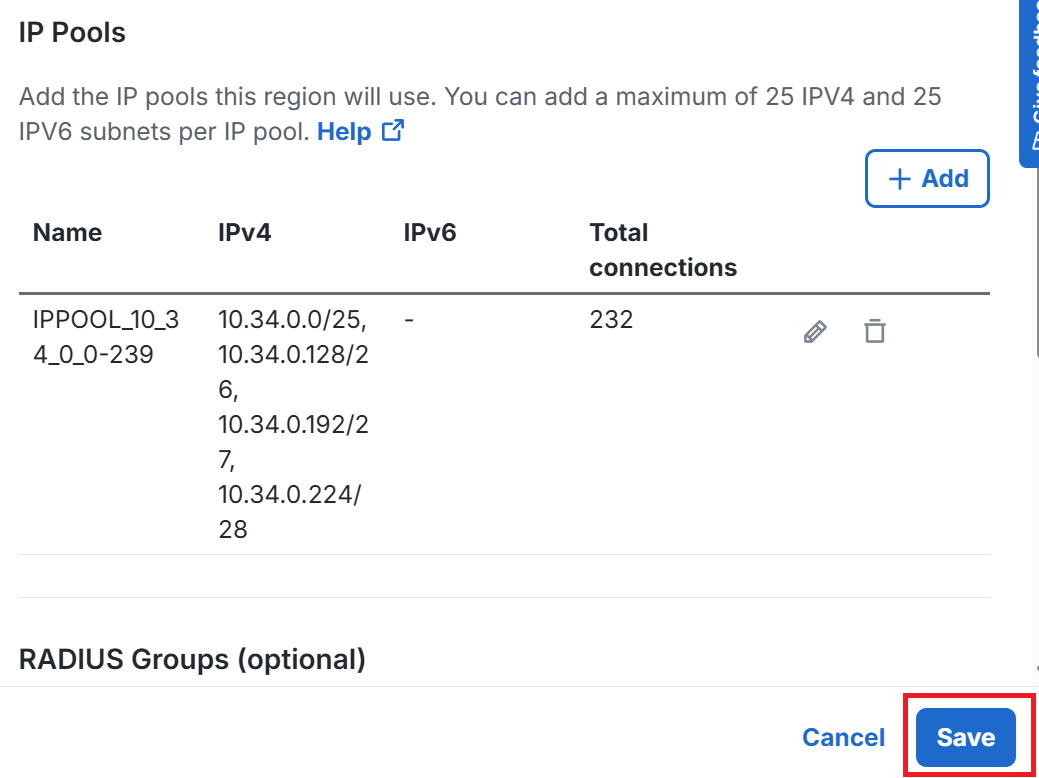
⑦Back on the original screen, the IP pool settings are now reflected, so click Save.
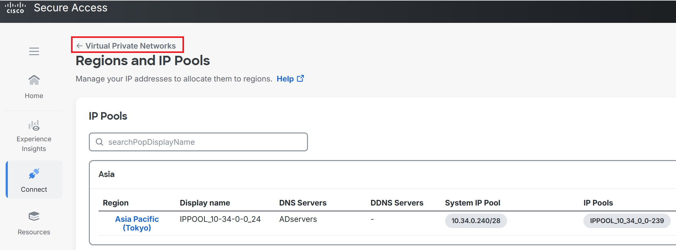
⑧Go to Virtual Private Networks.
Creating a VPN profile
|
Next, we'll create a profile for the VPN connection. |
①Go to Connect → End User Connectivity → + VPN Profile.
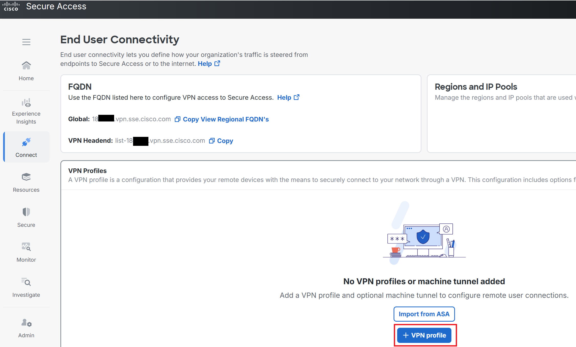
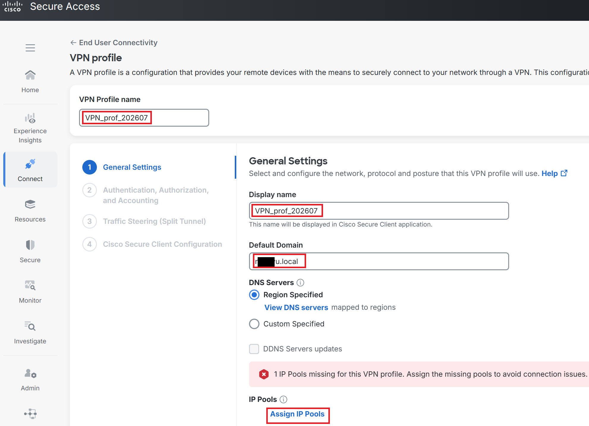
②Enter any name you like for VPN Profile name. This time I used VPN_prof_202607.
Set Display name under General Settings to VPN_prof_202607 as well. This is the name that will be displayed in the client software (secure client) installed on each PC.
Enter any value you like for Default Domain too. This time I used the domain in use on the AD server.
Click Assign IP Pools under IP Pools.
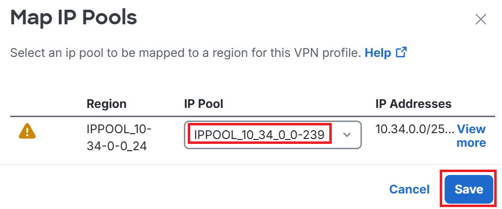
③The screen below appears on the right side of the display.
Select the IP to issue to client endpoints. This time, as shown in the red box, I selected IPPOOL_10_34_0_0-239, then clicked Save.
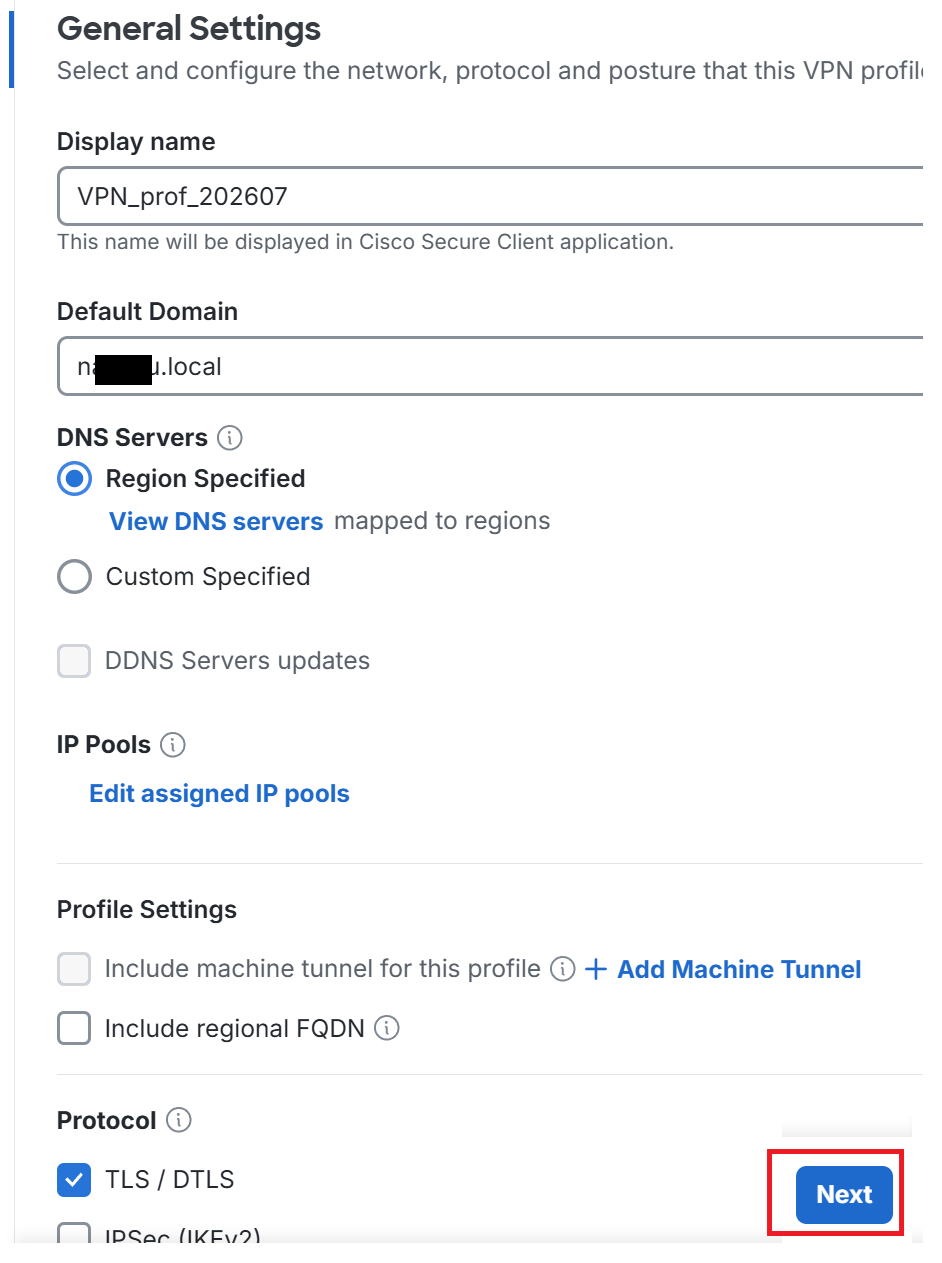
④Back on the original screen, click Next.
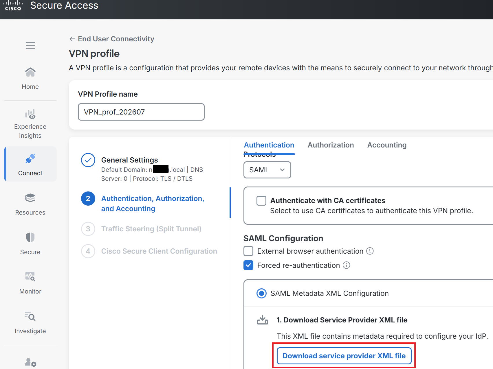
⑤Click Download Service Provider XML file to download the XML file.
File name: VPN_prof_202607_saml_metadata.xml
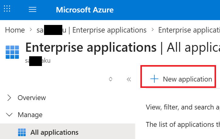
⑥Open the Entra ID screen and go to Enterprise applications → New application.
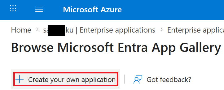
⑦Go to Create your own application.
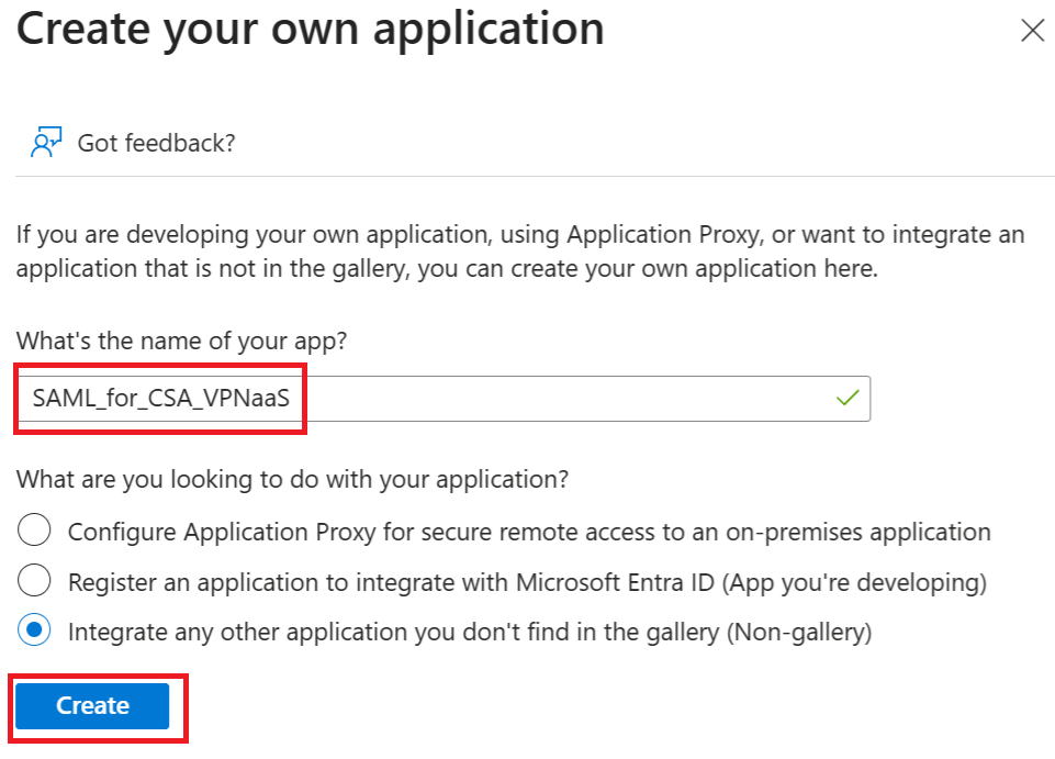
⑧Enter any app name you like. This time I used SAML_for_CSA_VPNaaS. Then click Create.
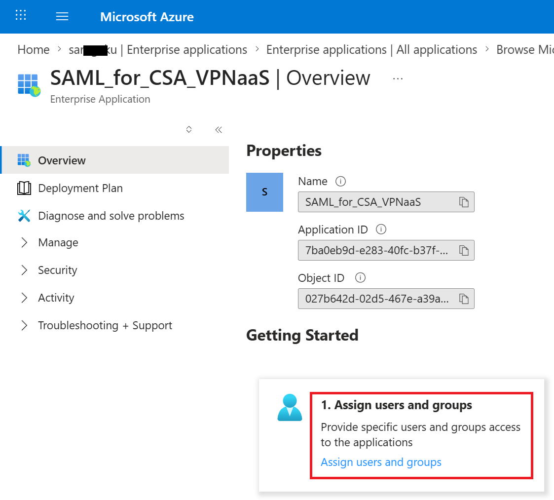
⑨Go to Assign users and groups.
⑩Go to Add user/group.
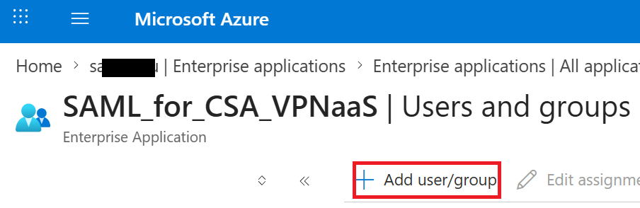
⑪Go to None Selected.
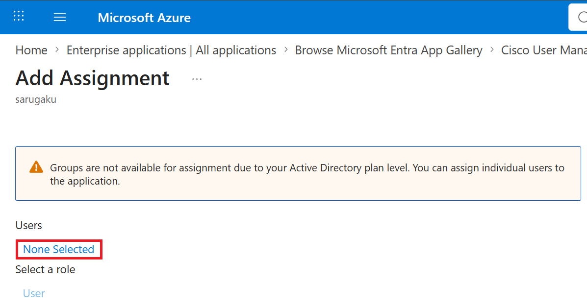
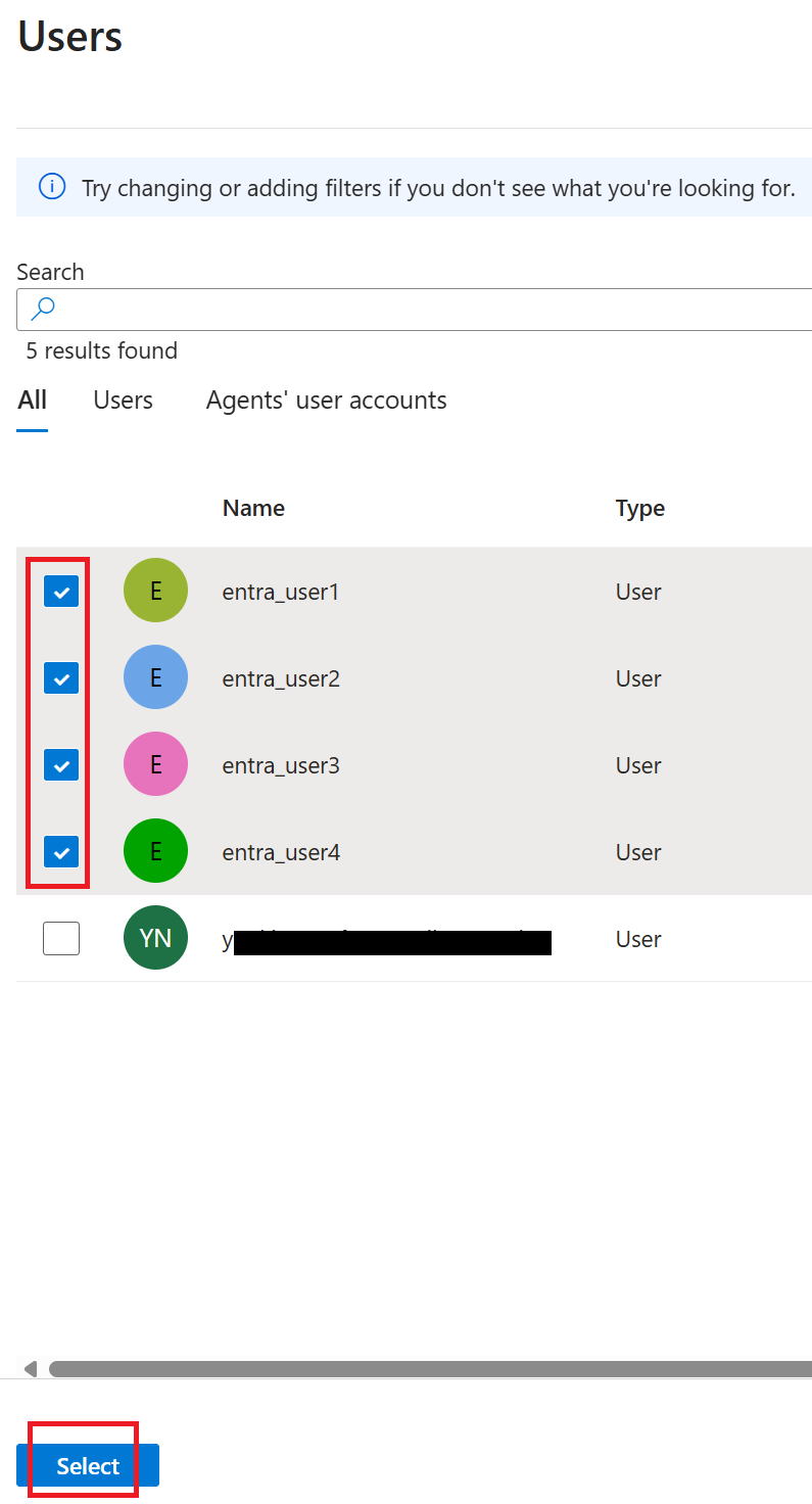
⑫The screen below appears on the right side of the display. This time I selected entra_user1 through entra_user4 and clicked select at the bottom left.
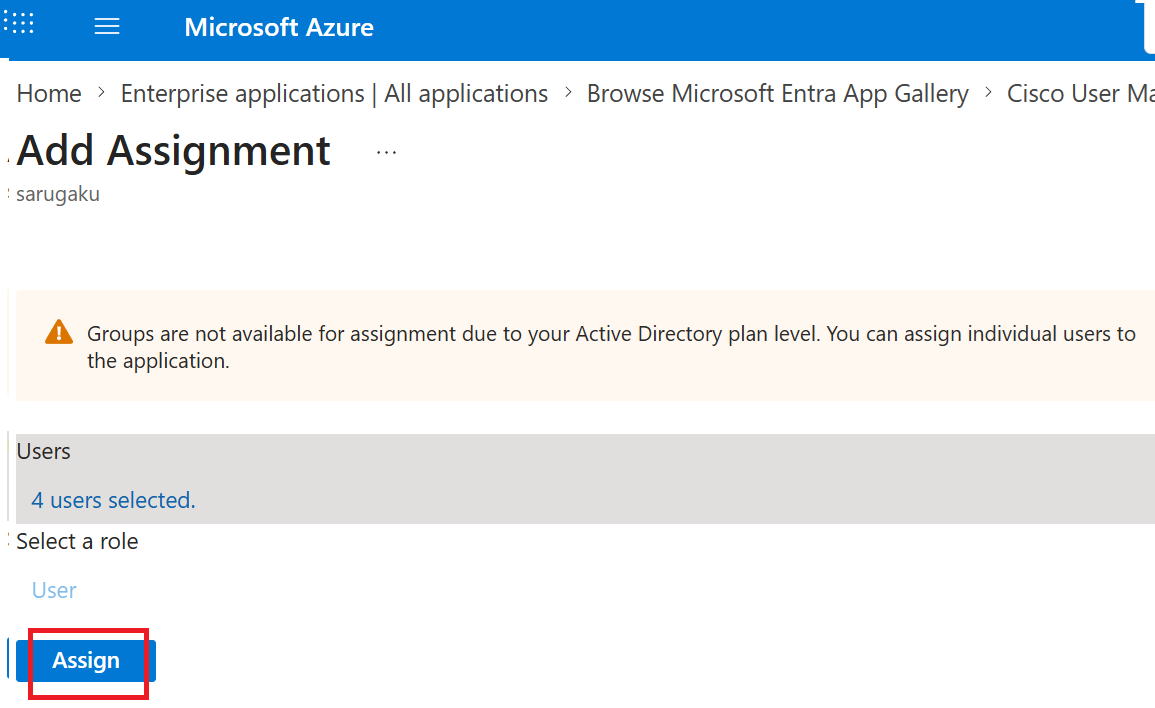
⑬Go to Assign.
⑭Go to Single Sign-on.
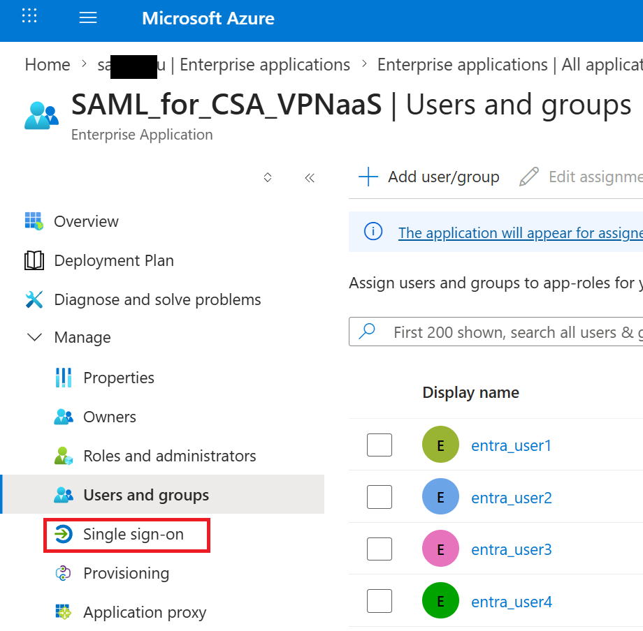
⑮Go to SAML.
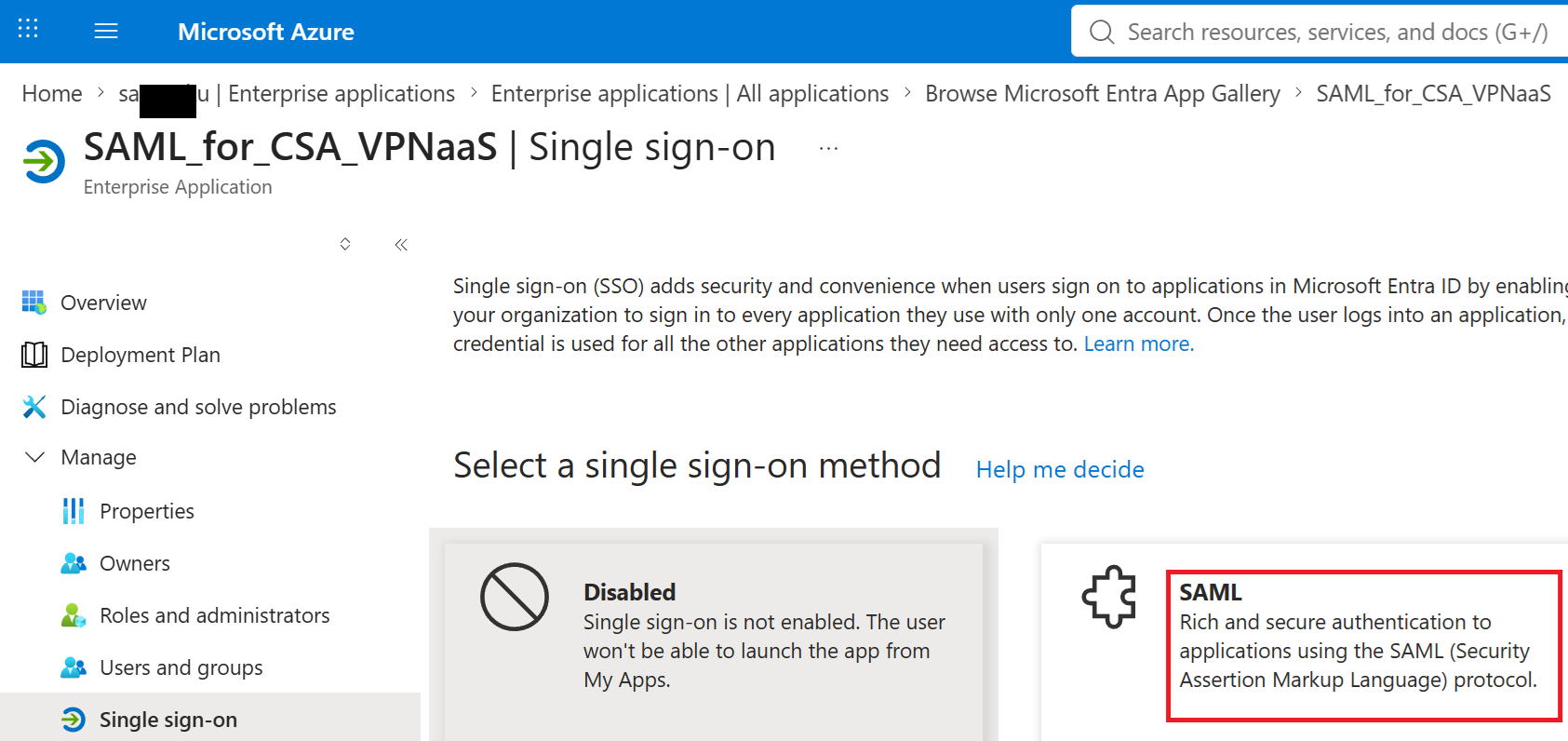
⑯Go to Upload metadata file and upload the XML file (VPN_prof_202607_saml_metadata.xml) you downloaded from Secure Access earlier.
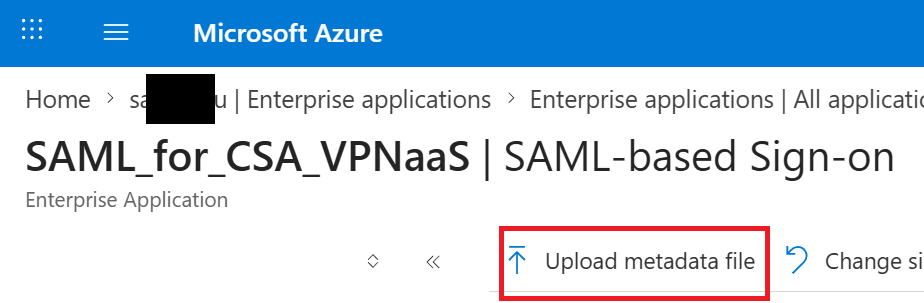
⑰Go to Download under Federation Metadata XML.
File name: SAML_for_CSA_VPNaaS.xml
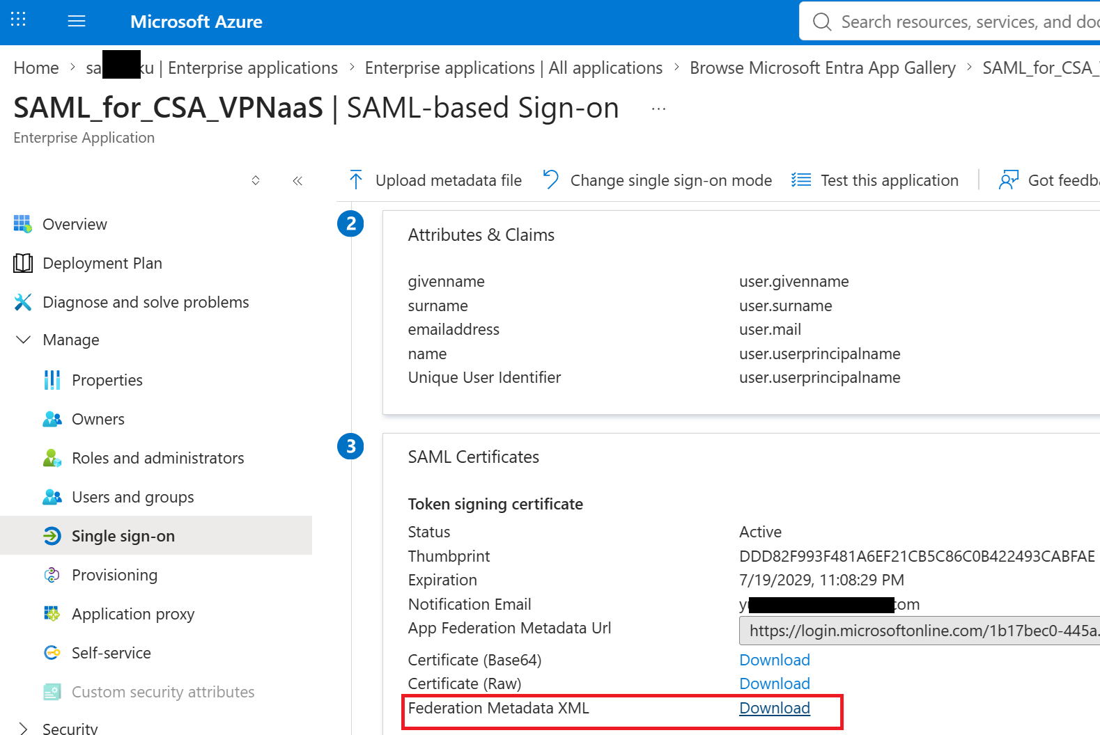
⑱Upload the XML file (SAML_for_CSA_VPNaaS.xml) you downloaded from Entra ID, then click Next.
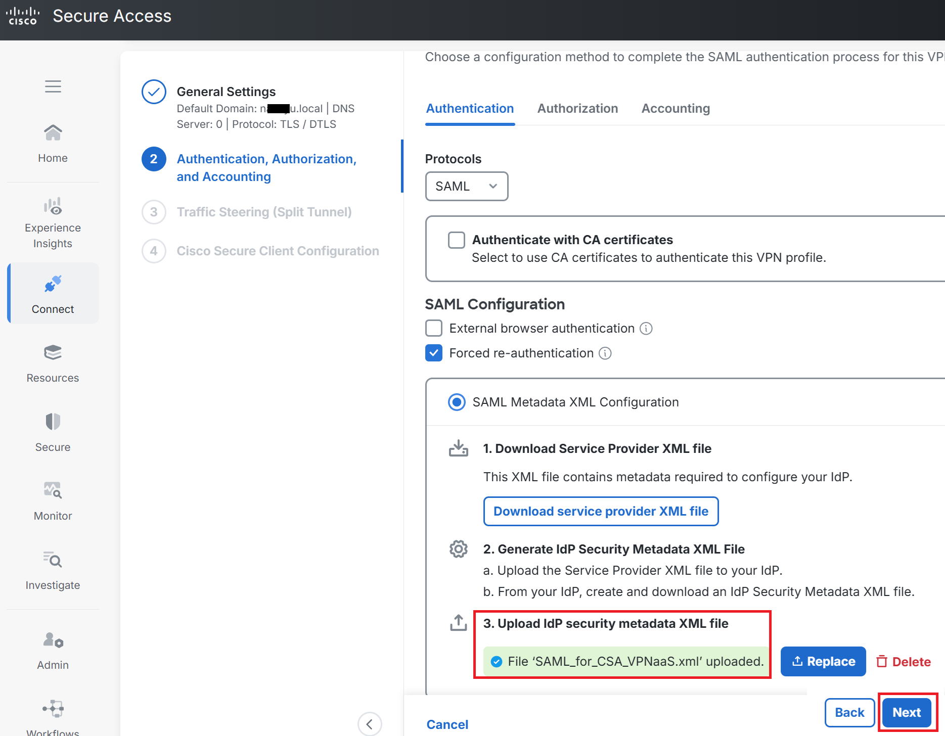
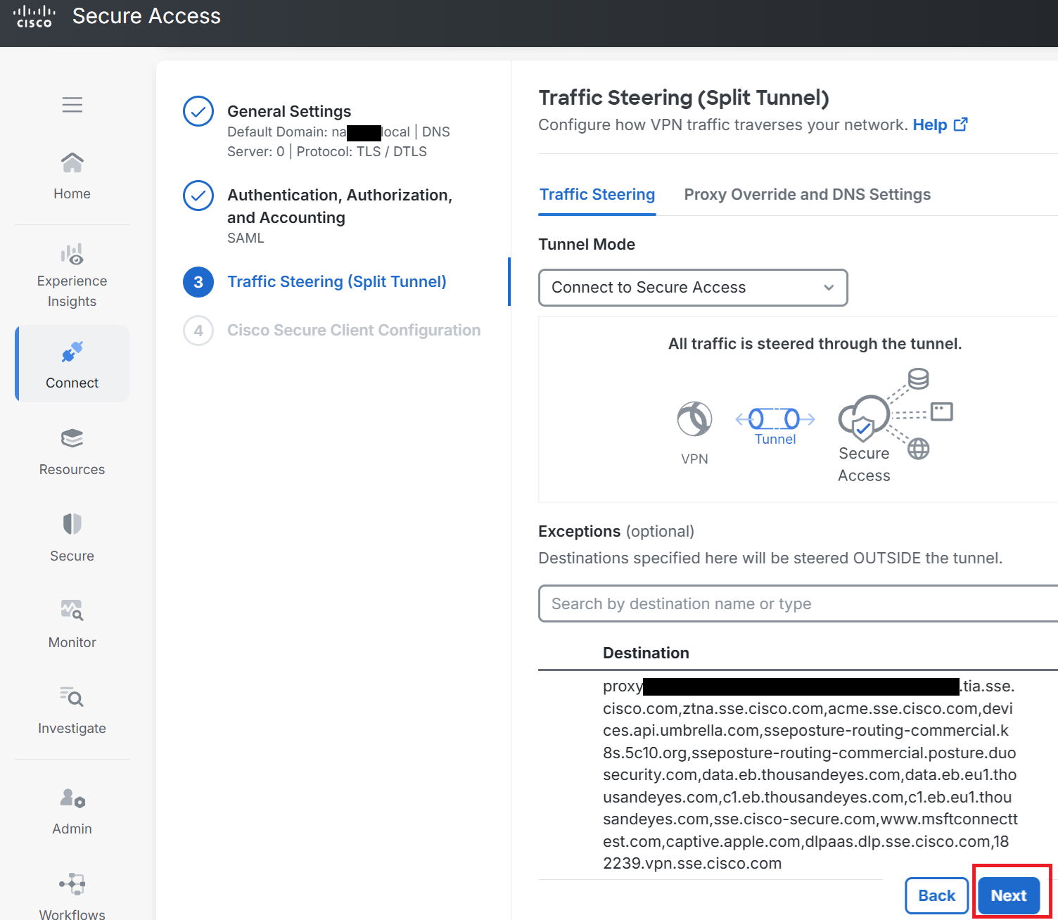
⑲Click Next as-is.
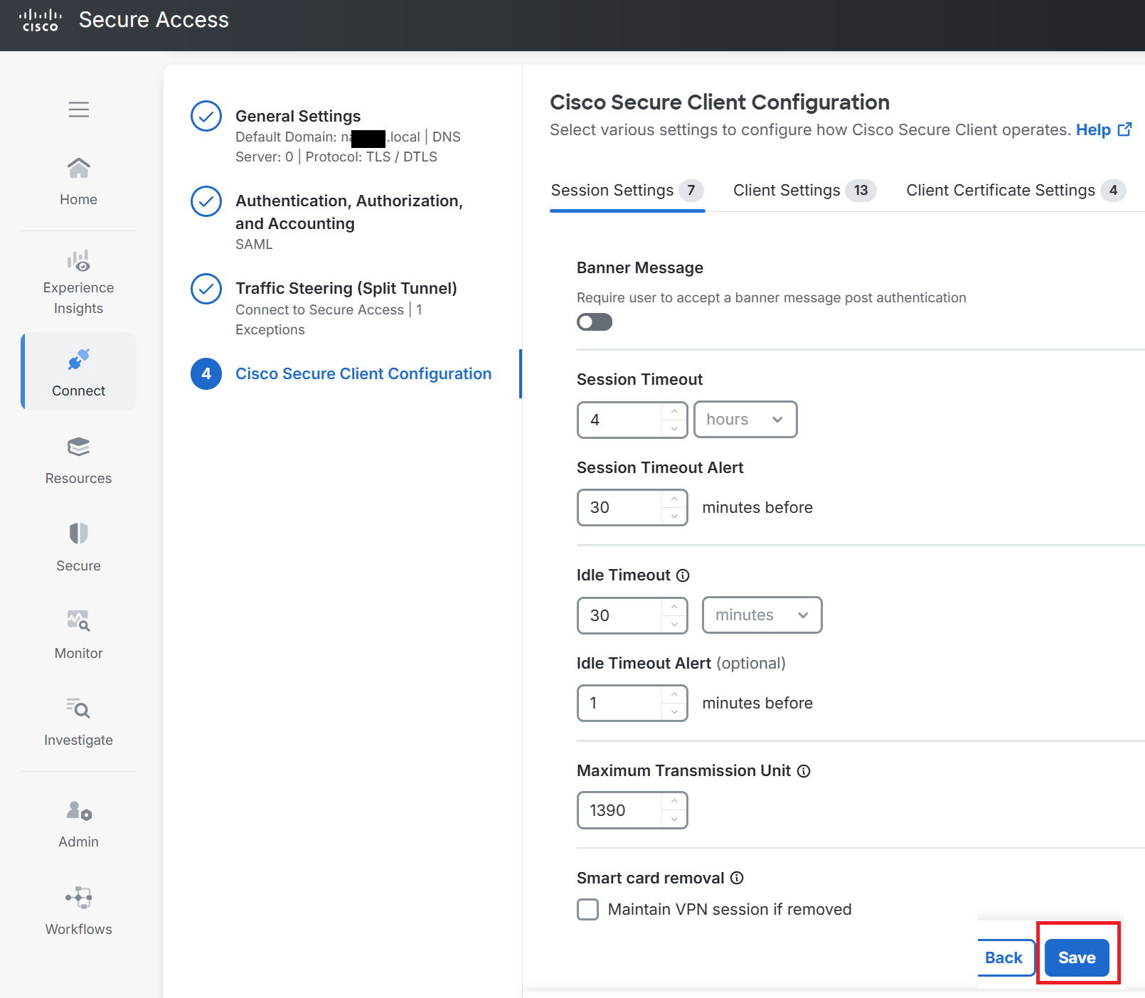
⑳Click Save as-is.
Creating a Private Resource
|
Next, we'll create a Private Resource. This is a type of Firewall object-creation feature, used to specify the destinations that remote access can reach. This time we'll create AWS's 172.17.1.0/24 subnet as a Private Resource. |
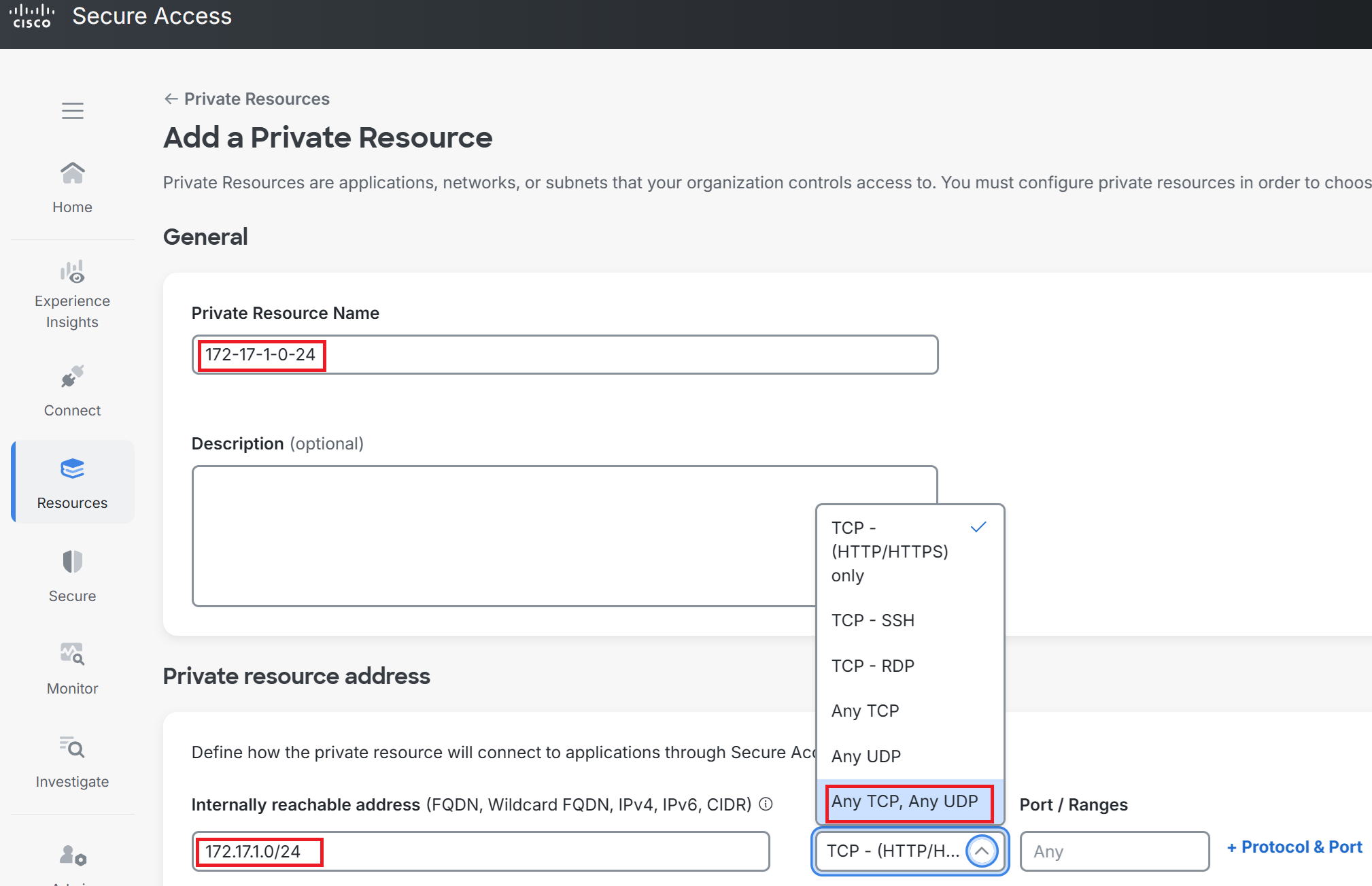
①Go to Resources → Private Resources → Add a Private Resource.
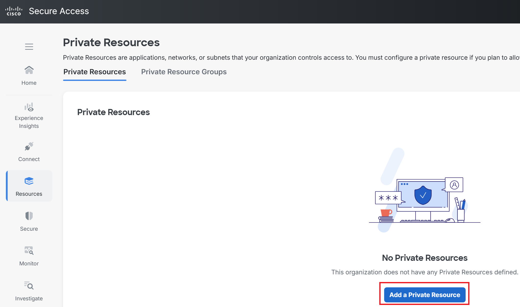
②Enter any Private Resource Name you like. This time I used 172-17-1-0-24.
For Internally reachable address, enter AWS's subnet, 172.17.1.0/24.
Select Any TCP,Any UDP for Protocol.
*This also allows ICMP through, not just TCP and UDP.
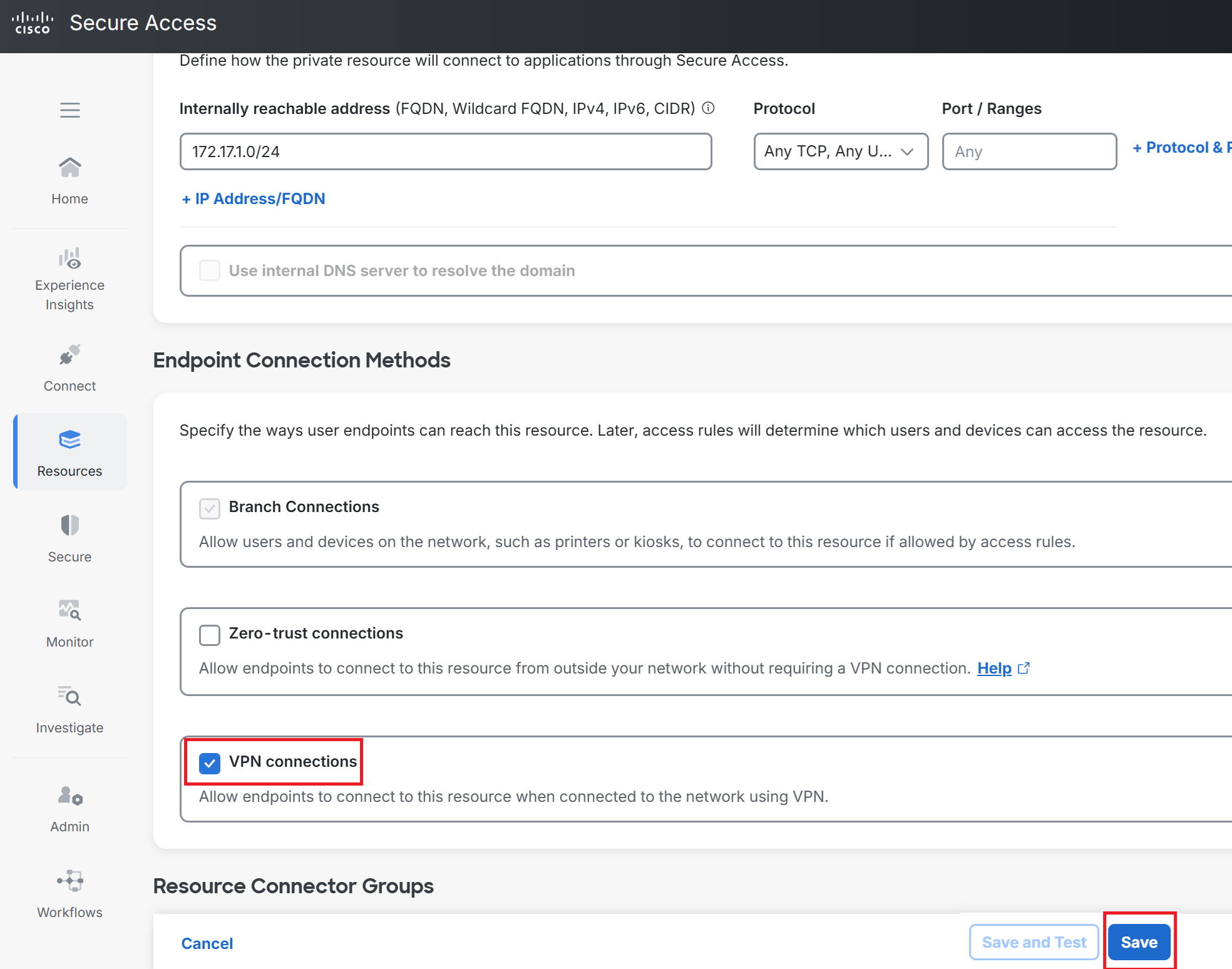
③Scroll down on the previous screen, check VPN connections, and click Save.
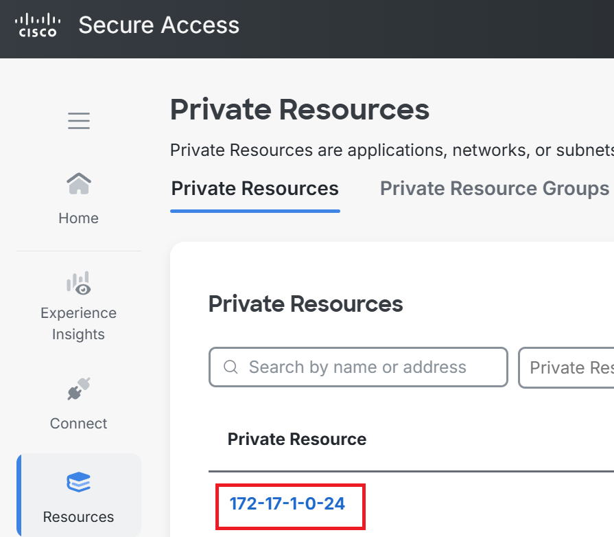
④The Private Resource has been created.
Creating an Access policy
|
Next, we'll create an Access Policy, which is a packet filtering rule. Since remote access traffic (Private Access) has an implicit deny in place by default, communication won't be possible unless you create a policy that explicitly allows it. This time, we'll create a policy that allows all traffic from "the users imported from Entra ID" to "AWS's 172.17.1.0/24 subnet". |
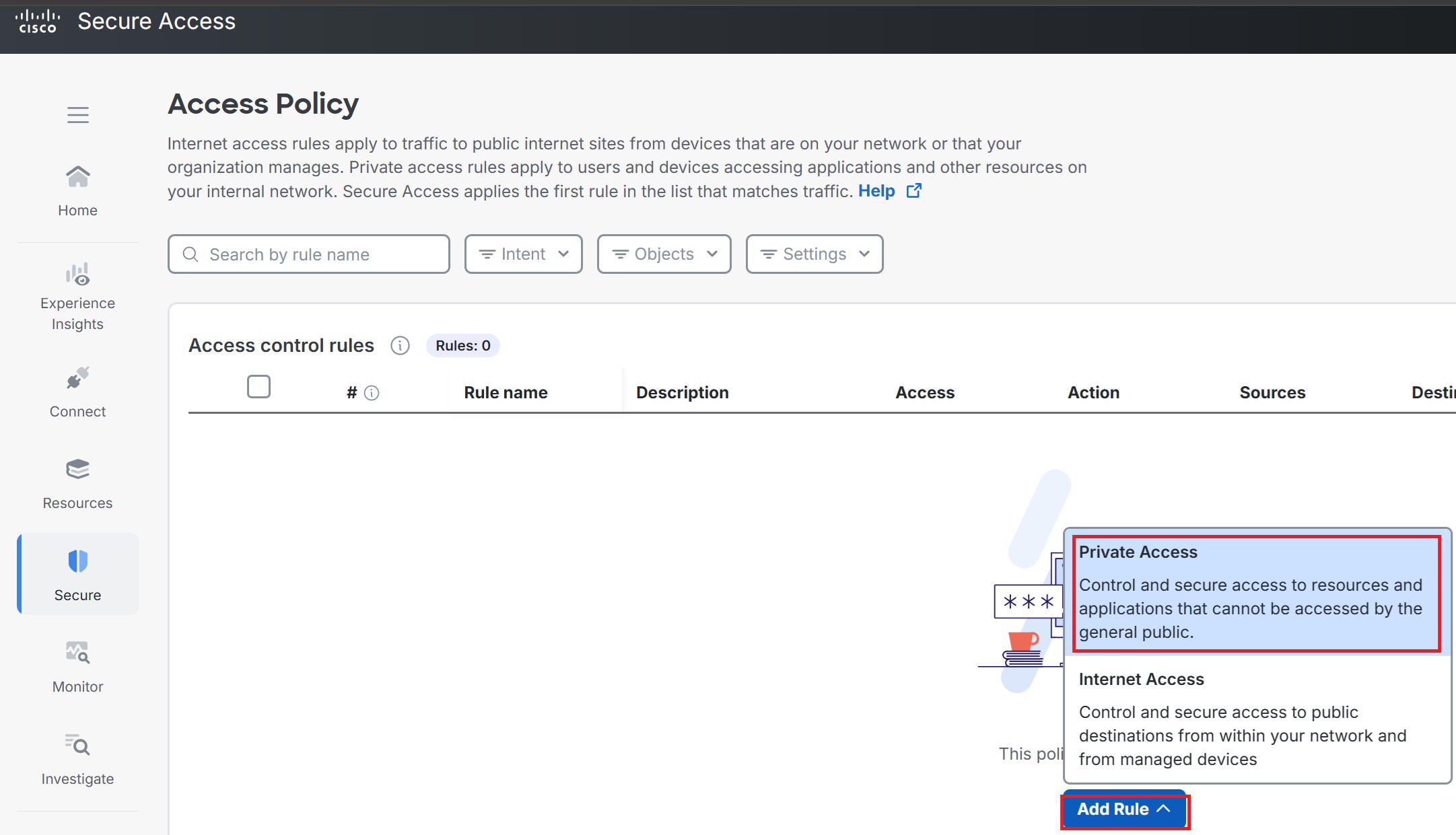
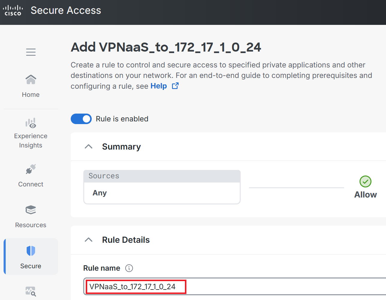
①Go to Secure → Access Policy → Add Rule → Private Access.
②Enter any name you like for Rule name. This time I used VPNaaS_to_172_17_1_0_24.
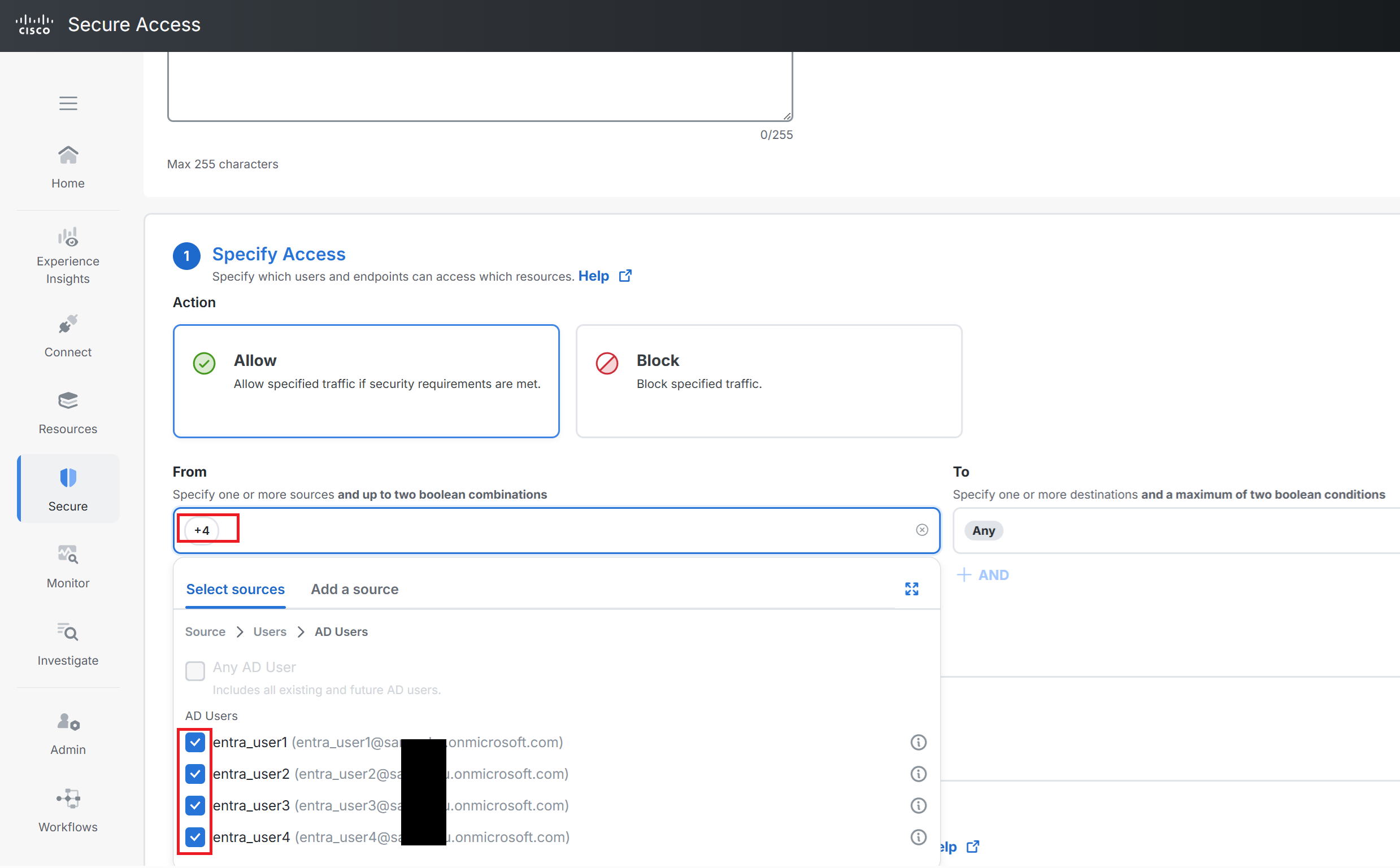
③Scroll down on the previous screen to From. This time I selected entra_user1 through entra_user4.
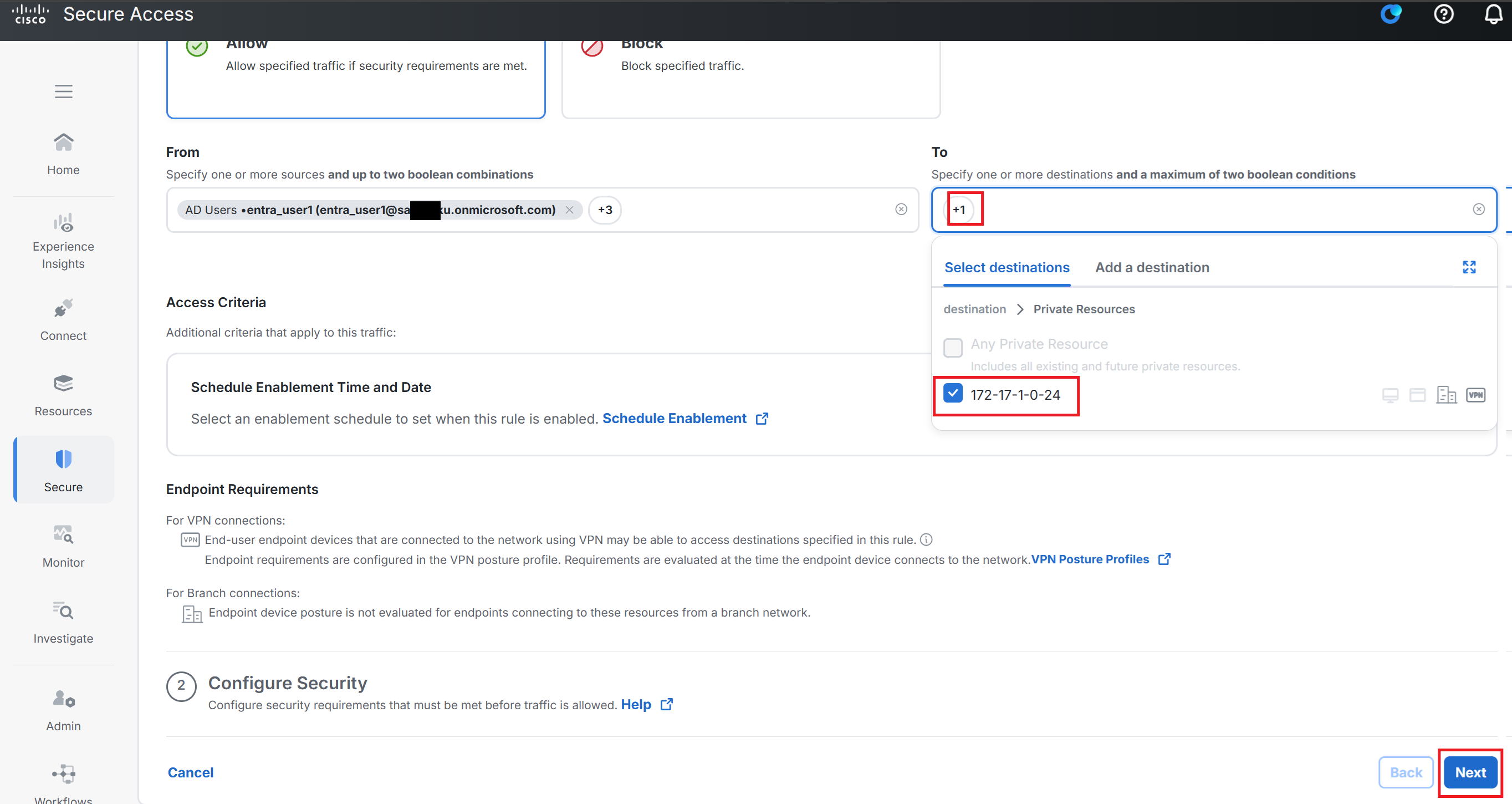
④For To, select 172-17-1-0-24, which we created earlier. Then click Next.
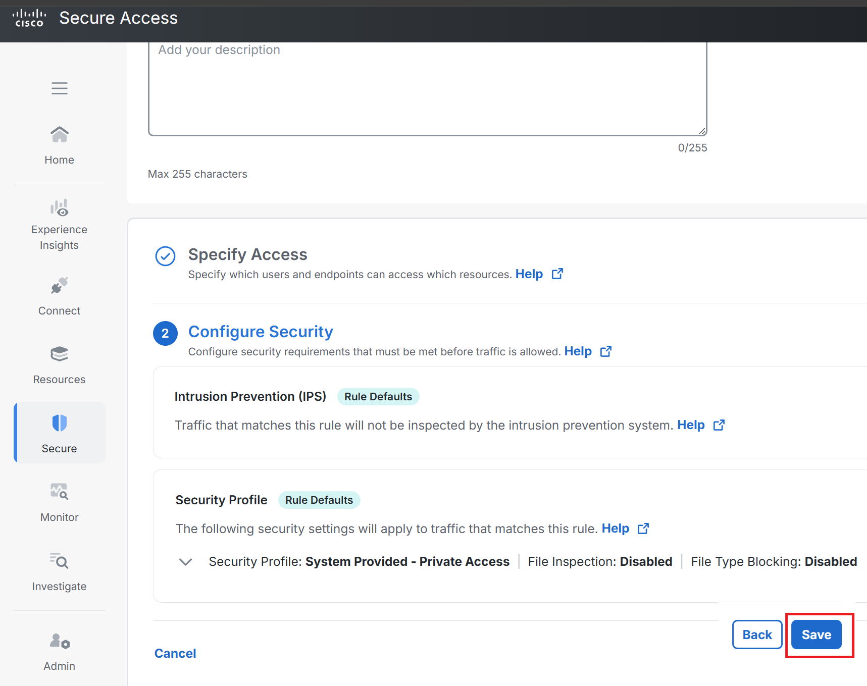
⑤Click Save as-is.
Installing Secure Client
|
Next, we'll look at how to install Secure Client, the dedicated client software, on PC1. |
①Go to Connect → End User Connectivity → Cisco Secure Client.
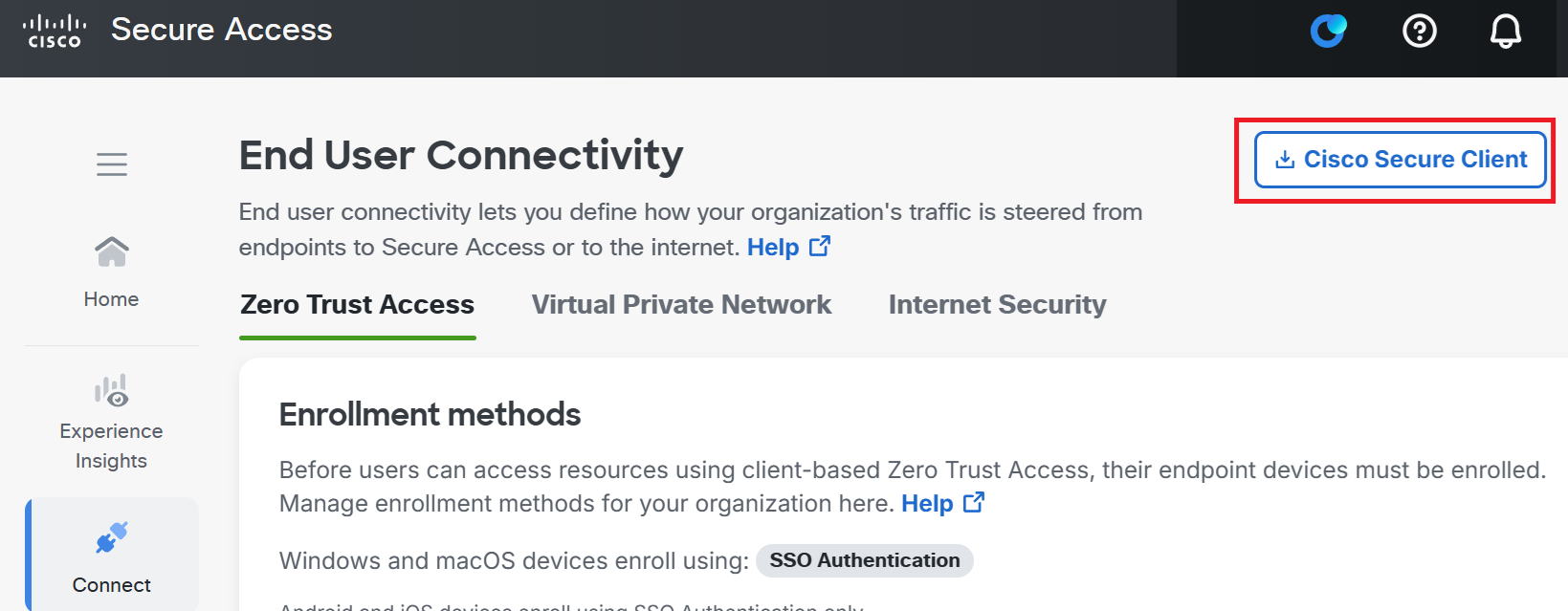
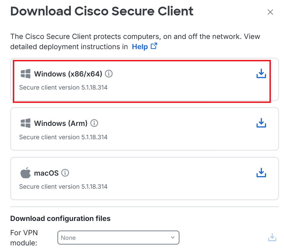
②The test PC this time is Windows 11 64-bit, so click the item in the red box.
cisco-secure-client-win-5.1.18.314-predeploy-k9.zip is downloaded, so extract it.
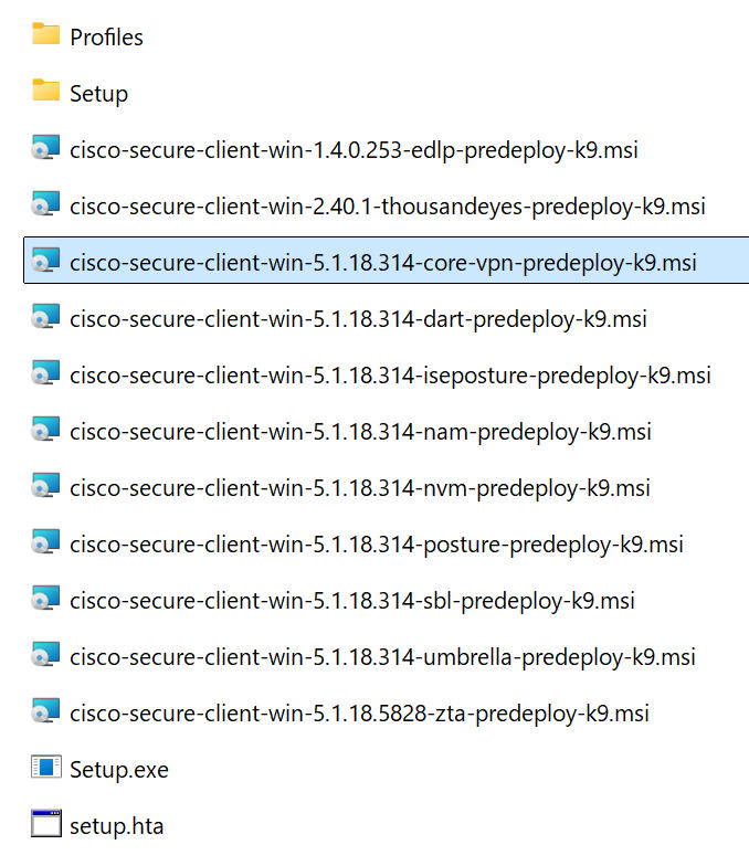
③Extracting the ZIP file gives you what's shown below. Move all the msi files to the test PC.
*As shown below, secure client has a separate installer for each feature. That means you install using whichever installer matches the feature you need. For the testing on this page, cisco-secure-client-win-5.1.18.314-core-vpn-predeploy-k9.msi alone would be enough, but I'll move all of them over just in case.
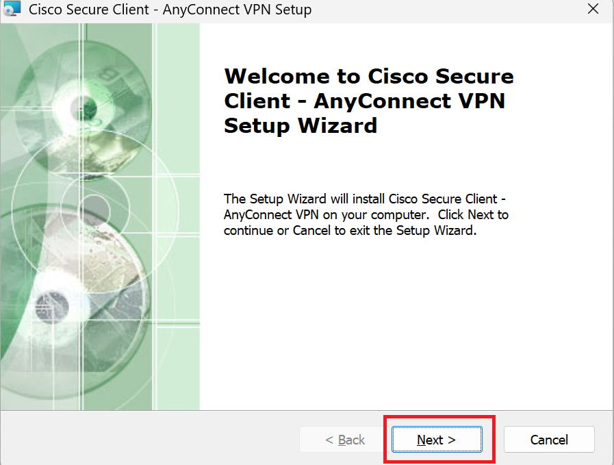
④Opening cisco-secure-client-win-5.1.18.314-core-vpn-predeploy-k9.msi displays the screen below, so click Next.
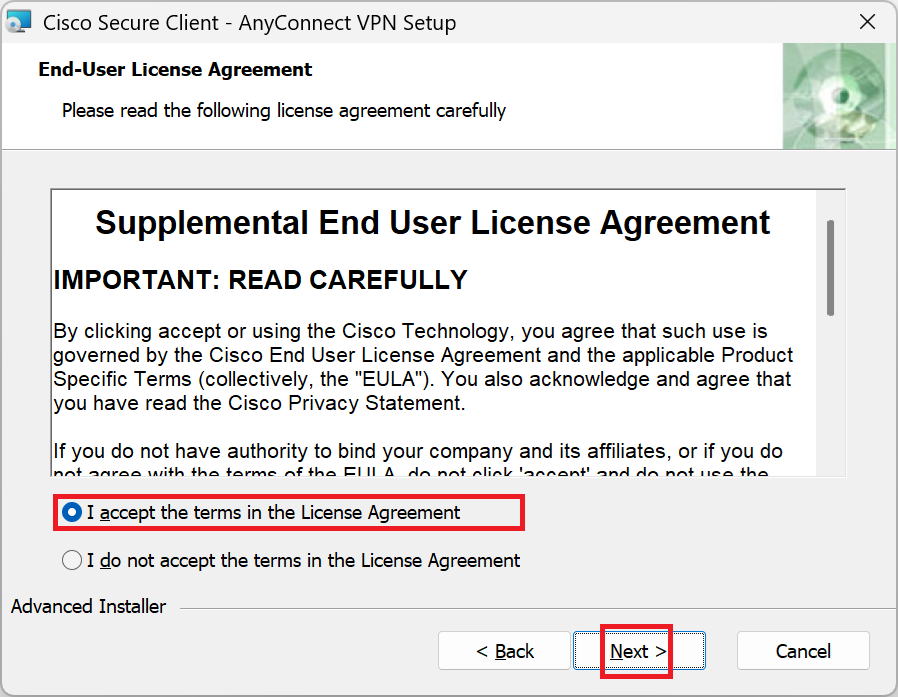
⑤Check Accept and click Next.
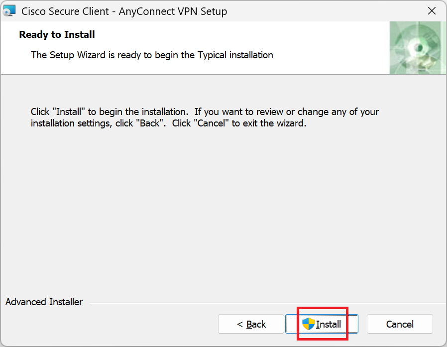
⑥Go to Install. Once the Finish button appears, click Finish to complete.
Trying a VPN connection
|
Next, we'll look at how to establish the VPN connection. |
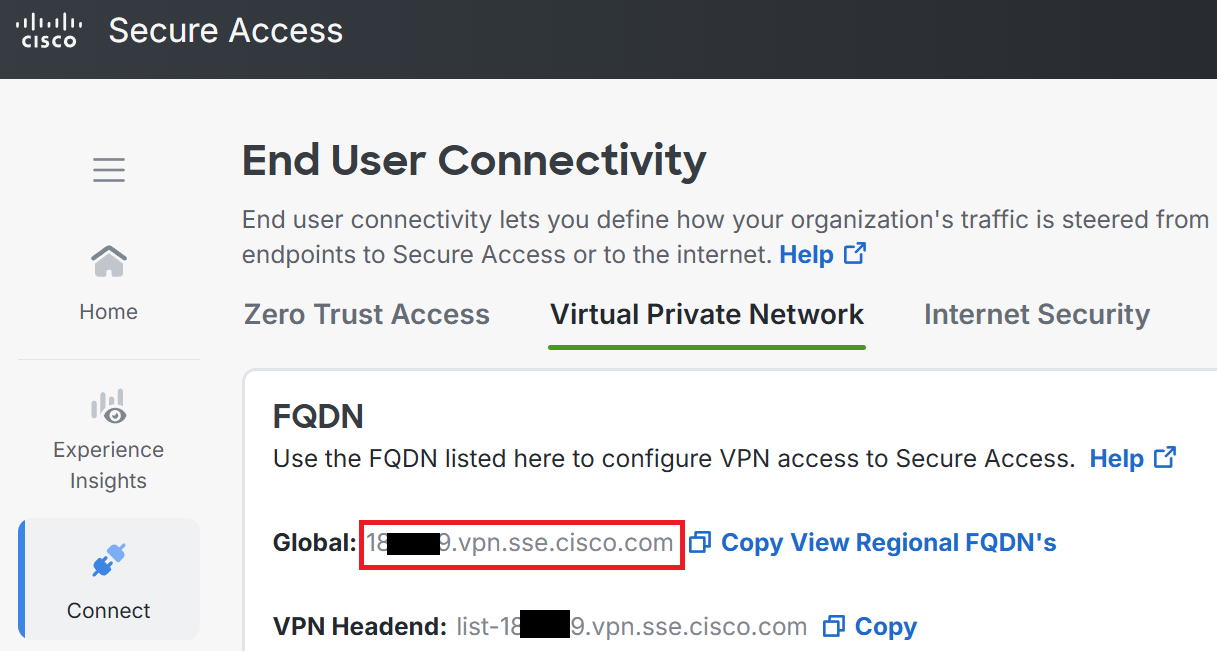
①Note down the FQDN for the VPN connection, shown in the red box.
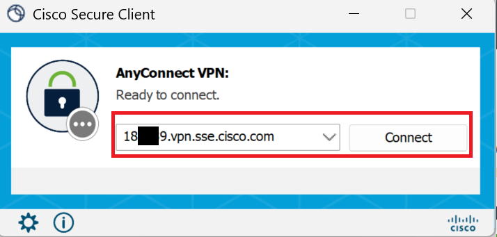
②Launch Secure Client, enter the VPN connection FQDN you copied earlier, and click Connect.
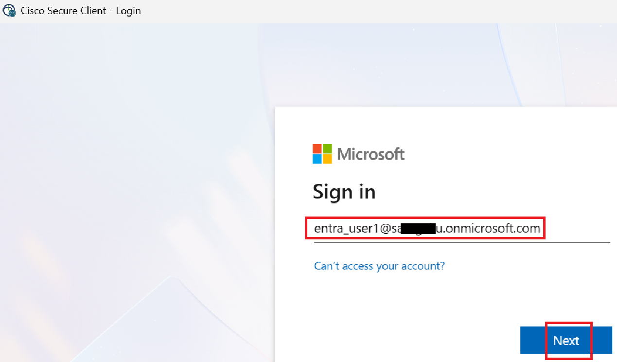
③The Entra ID login screen appears. Enter your account and click Next, then enter your password as well.
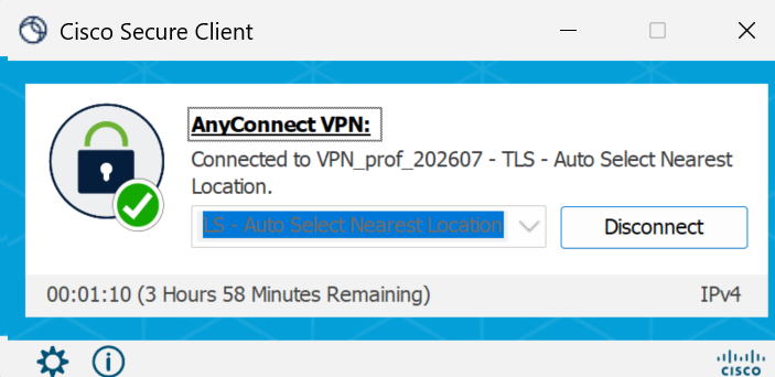
④The connection completed successfully.
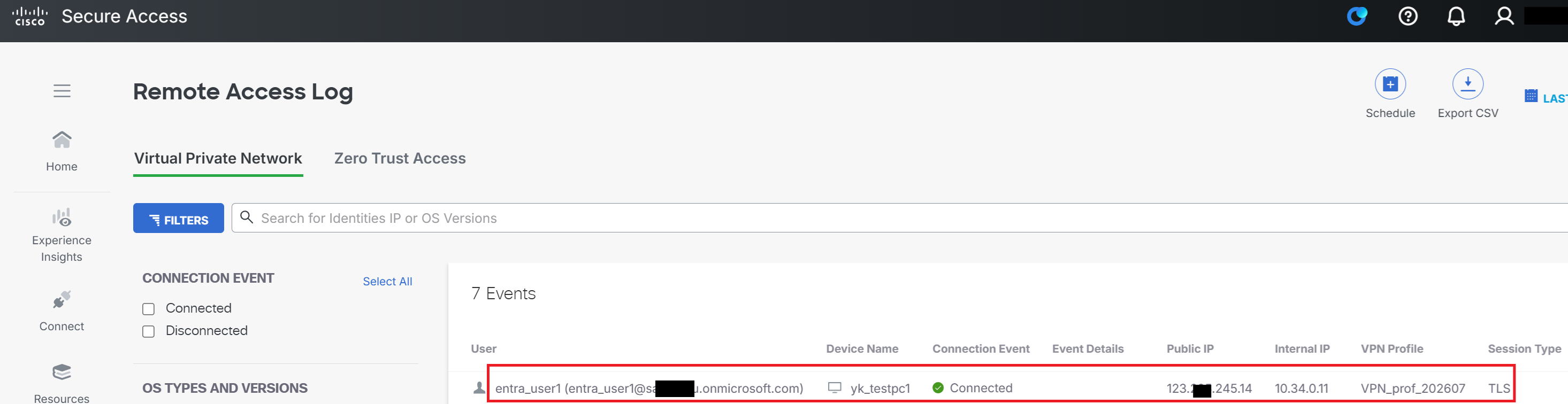
⑤Going to Monitor → Remote Access Log shows the log of the VPN connection. The endpoint has been assigned 10.34.0.11.
Verification
|
Finally, let's verify things are working. As shown in the diagram below, let's try Ping, Trace, and RDP (Remote Desktop) from PC1 to AD1. |
| PC1 → AD1 Ping OK! |
| C:\Users\sirtu>ping 172.17.1.90 Pinging 172.17.1.90 with 32 bytes of data: Reply from 172.17.1.90: bytes=32 time=12ms TTL=122 Reply from 172.17.1.90: bytes=32 time=11ms TTL=122 |
| PC1 → AD1 Trace OK! |
| C:\Users\sirtu>tracert -d 172.17.1.90 Tracing route to 172.17.1.90 over a maximum of 30 hops 1 8 ms 5 ms 5 ms 169.254.131.2 2 7 ms 7 ms 6 ms 10.108.8.1 3 8 ms 8 ms 7 ms 10.108.8.2 4 9 ms 9 ms 9 ms 10.117.8.2 5 * * * Request timed out. 6 * * * Request timed out. 7 13 ms 10 ms 11 ms 172.17.1.90 |
|
Both Ping and Trace are OK. What are these addresses that show up partway through the Trace, like 10.108.8.1 and 10.117.8.2? |
|
I looked into it, but couldn't find the details. But since they're not addresses I'm using in AWS or elsewhere, I think they're addresses Cisco uses internally within its system. Sometimes the addresses that show up in Trace results are management loopback addresses rather than ones used for actual traffic, so I suspect that's the case here too. Anyway, let's move on to RDP next. |
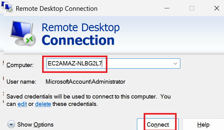
①Launch the RDP connection screen on PC1, enter AD1's hostname, "EC2AMAZ-NLBG2L7", and click Connect.
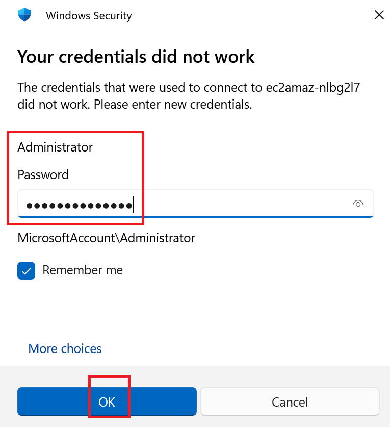
②A screen for entering your ID and password appeared; after entering them and proceeding, the RDP connection succeeded.
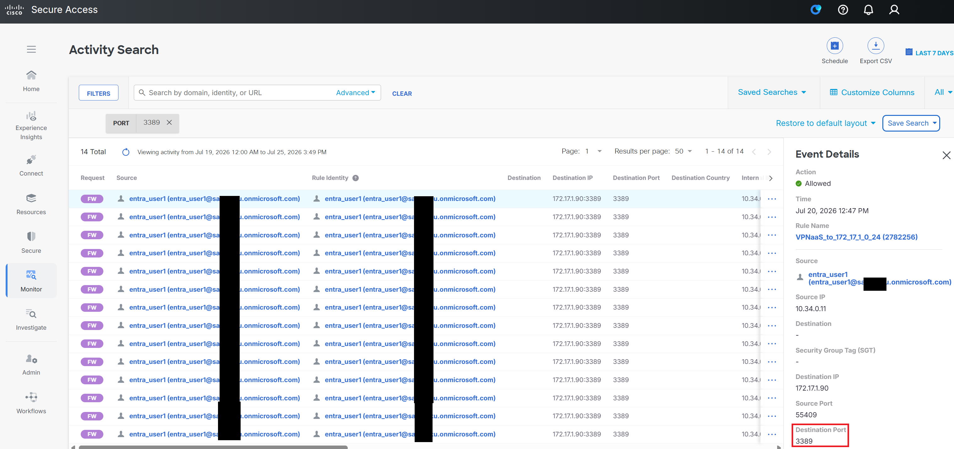
③Searching Activity Search for "port number: 3389" confirmed that the RDP communication log was successfully recorded.
|
Oh, so you can connect using the hostname too, not just the IP address. |
|
That's right. This time, when we created the VPN profile, we specified the internal DNS's IP address and the domain used by AD on AWS. So that's it for this time. It was a long one, but thanks for reading. Next time we'll look at Scenario 2: VPNaaS vs ZTNA. |