Last updated: 2026.9.6
| Contents of this page |
Purpose of this session
 |
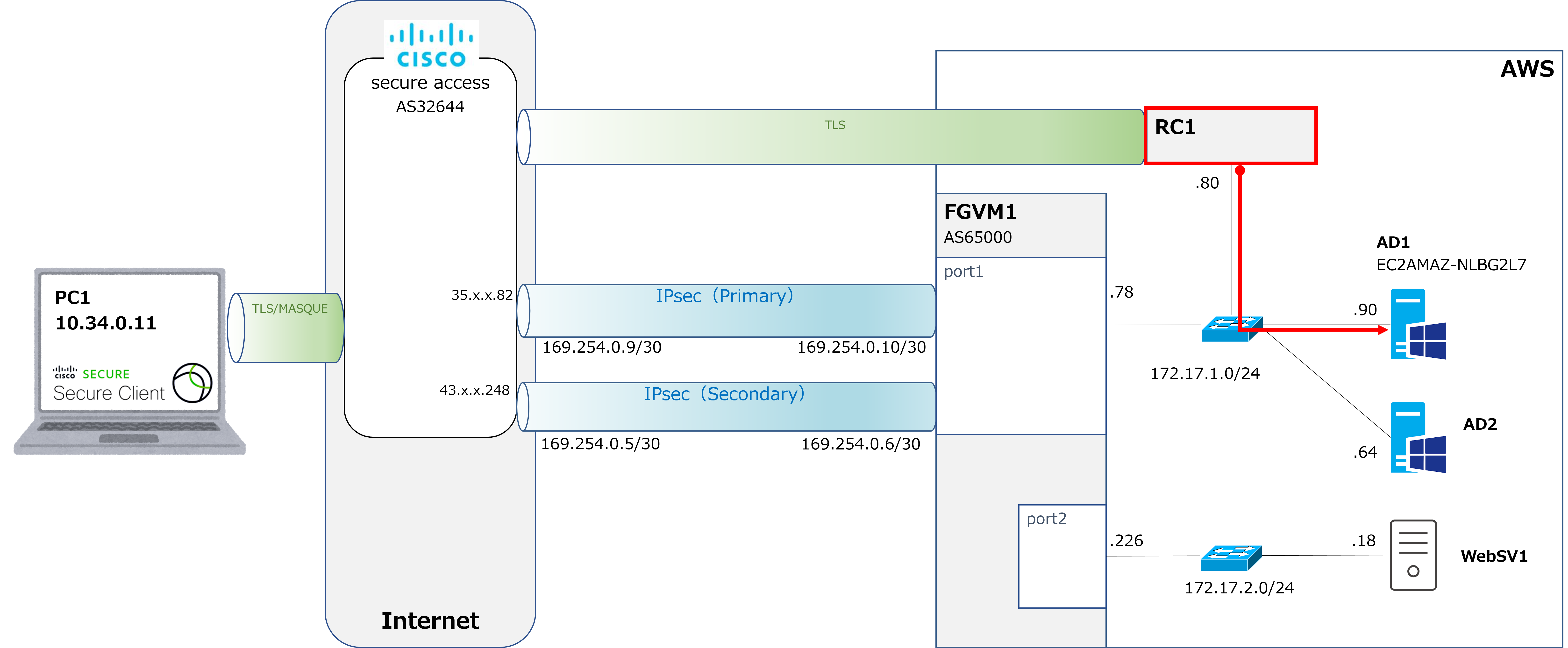
Continuing from last time, this is still Scenario 2: ZTNA-based remote access. When PC1 communicates with AD1 within AWS, instead of PC1 accessing AD1 via a VPN, the goal is to have RC1 communicate on its behalf, as shown by the red arrow in the diagram above. |
 |
So, PC1 can still get the result of that proxied communication, right? |
|
That's right. This time we'll look at how to configure that. |
Registering the internal DNS server
|
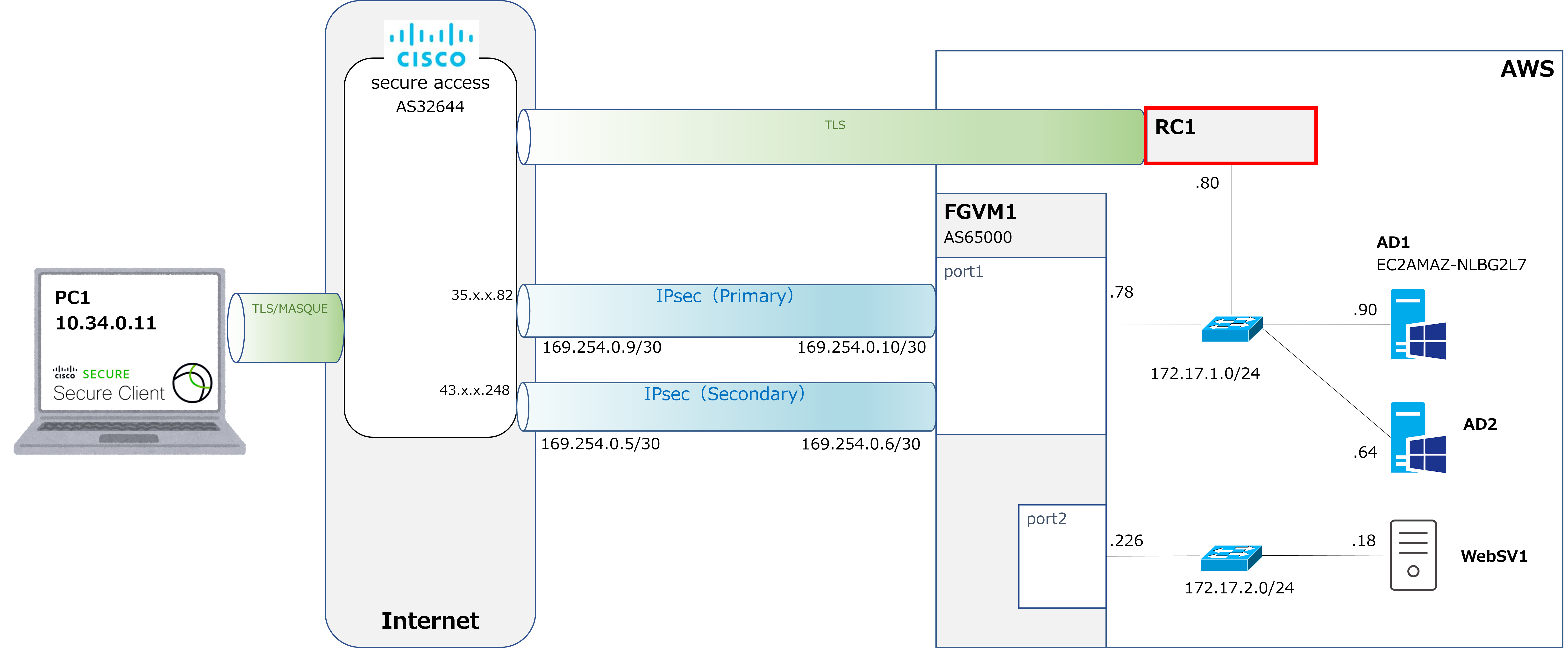
First, we'll build an RC (Resource Connector) at the location marked in red. Since the build process includes a step where you select the DNS server the RC will use, we'll register the internal DNS server in advance (in this case, AD1 also serves as the DNS server). |
|
Huh? RC handles communication to the internal network on our behalf, right? Does it also handle DNS traffic on our behalf? |
|
That's right. For PC1 to communicate with internal resources, it needs to resolve their names first. With the VPNaaS approach, PC1 sends the DNS query directly to the internal DNS server, but with the ZTNA approach, the RC handles this DNS query on PC1's behalf as well. So, we'll start with the task of registering that internal DNS server. |
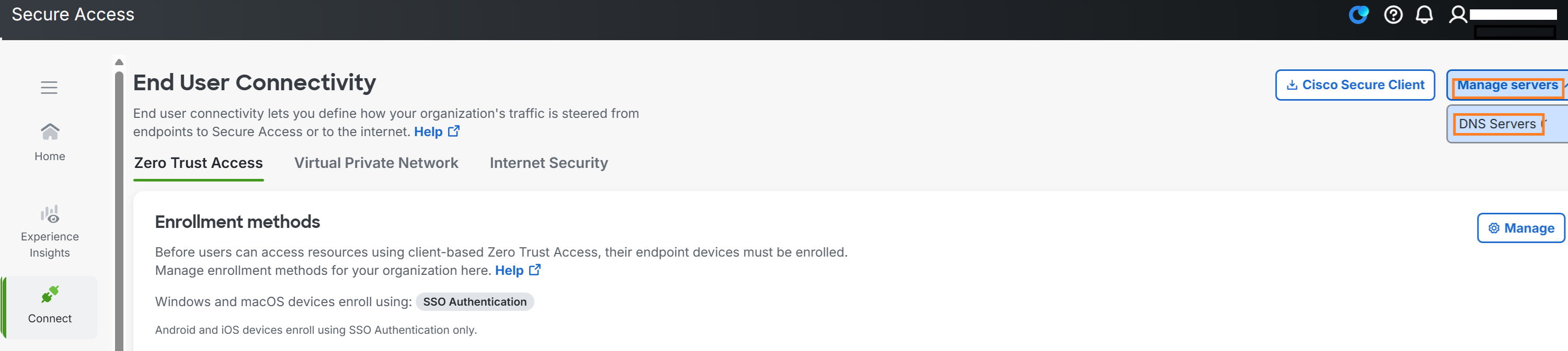
①Go to Connect → End User Connectivity → Manage servers → DNS Servers.
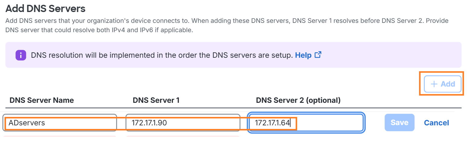
②Click +Add, enter the server name, server1, and server2, then click Save.
Building the RC
|
Now let's move on to building the RC itself. |
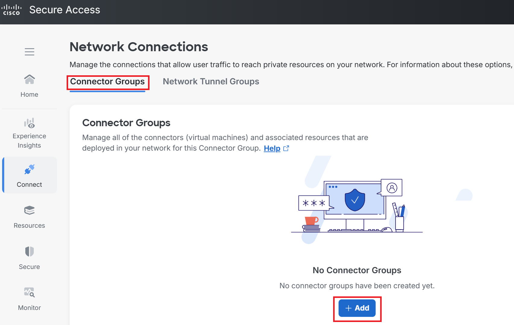
①Go to Connect → Network Connections → Connector Groups → +Add.
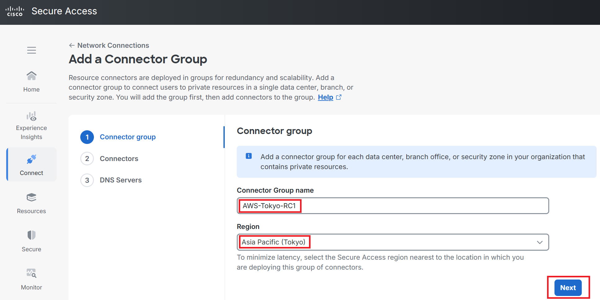
②Enter any name you like for the Connector Group name. This time I used AWS-Tokyo-RC1.
For Region (a bit confusing, but this is the Secure Access region, not the AWS region), I chose
Asia Pacific (Tokyo) this time. Then click Next.
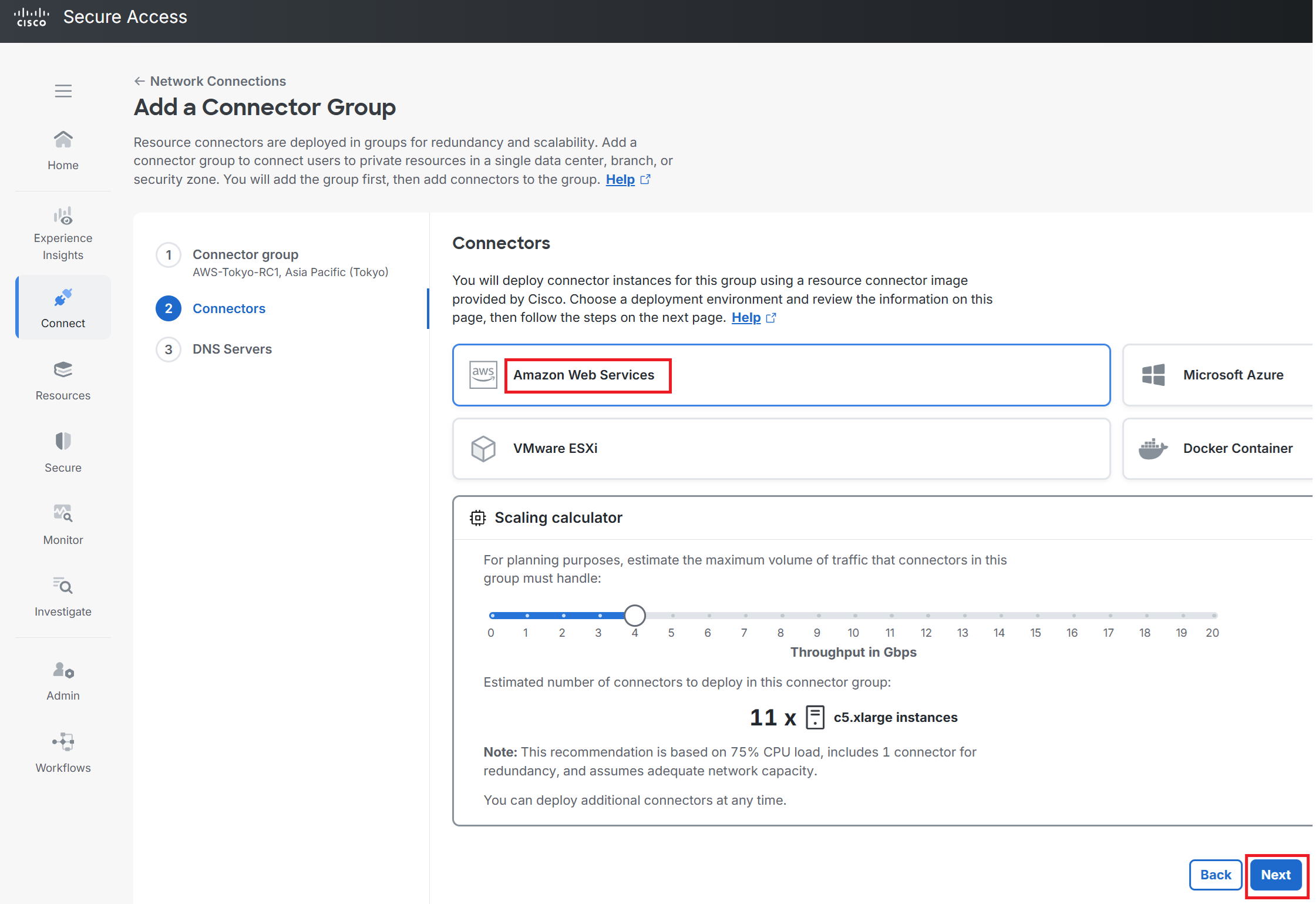
③Select where to build the Connector. This time I selected AWS.
Below that is a Scaling calculator. By default, as shown in the diagram, the expected throughput flowing through the RC is estimated at 4Gbps, and it's estimated that 11 c5.xlarge instances would be needed to handle that. This is just an estimate, so it's fine to click Next as-is. Since this is just a test setup with low traffic volume, we obviously don't need 11 instances—we'll just build one.
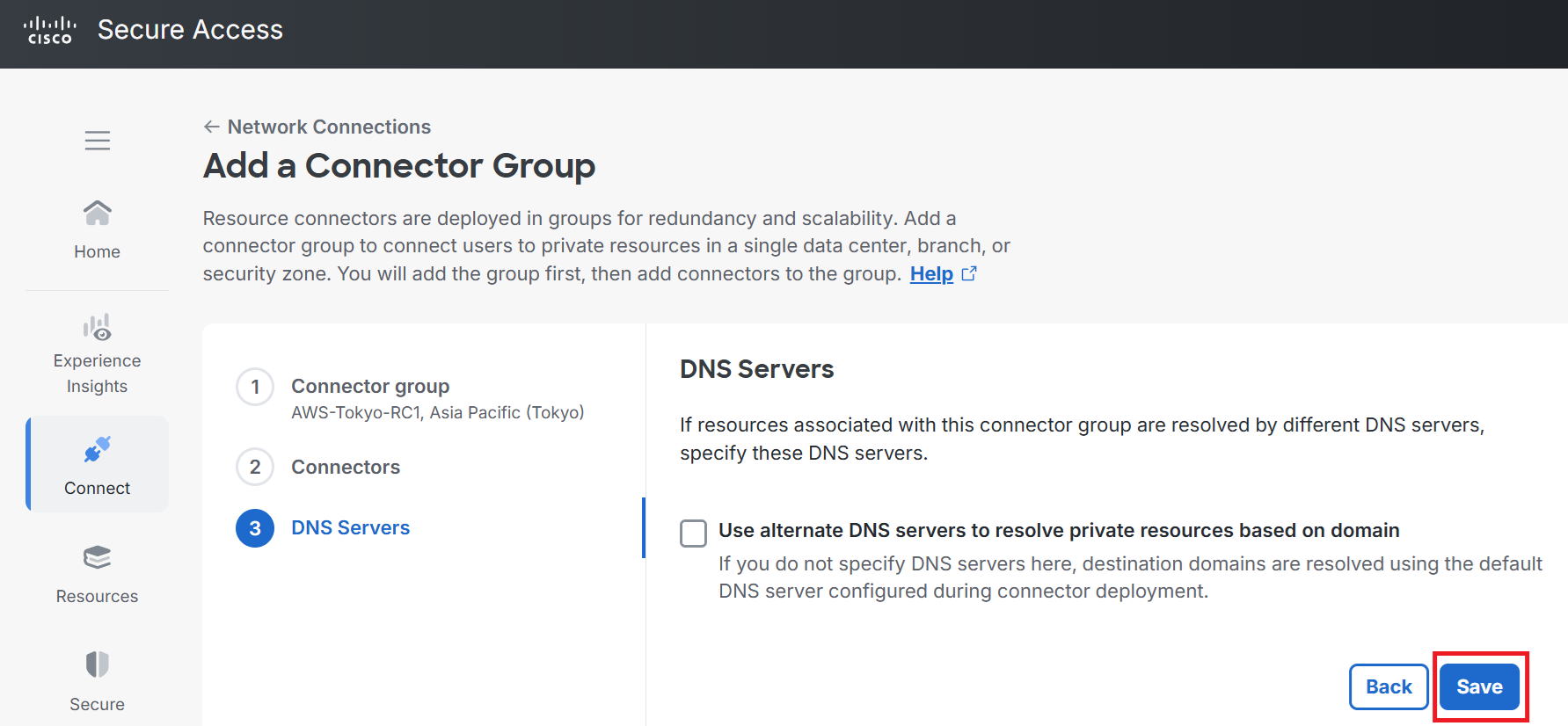
④Click Save as-is.
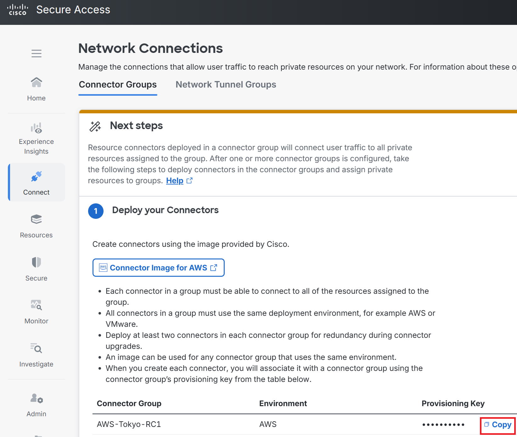
⑤Click Copy and note down the Provisioning Key.
|
From here, we'll move on to the work on the AWS side. |
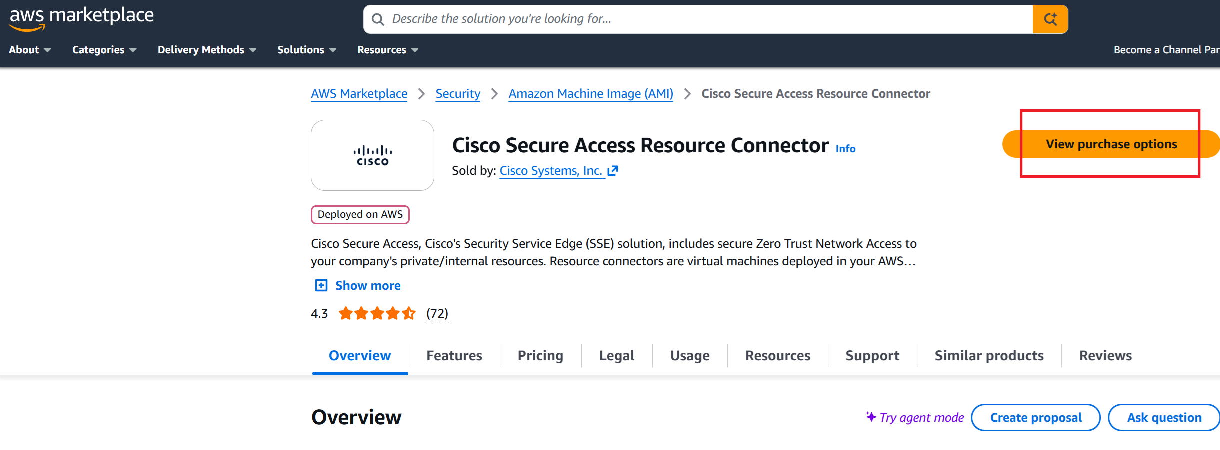
⑥Go to the AWS AMI page and click View purchase options.
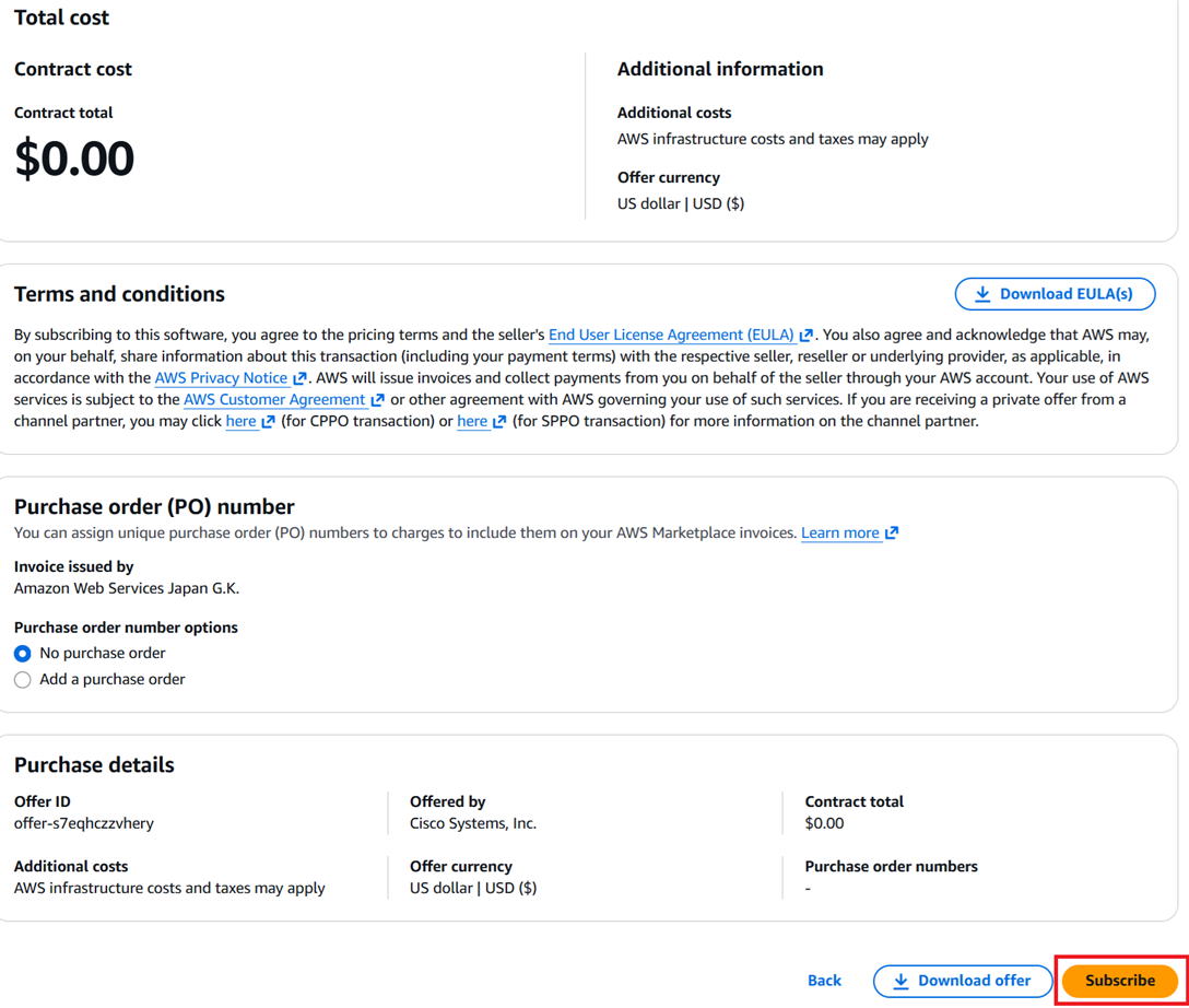
⑦It says $0.00. This means there's no contract fee or license fee.
You will still be charged for AWS resource usage (such as traffic charges and instance usage charges).
Click subscribe at the bottom right.
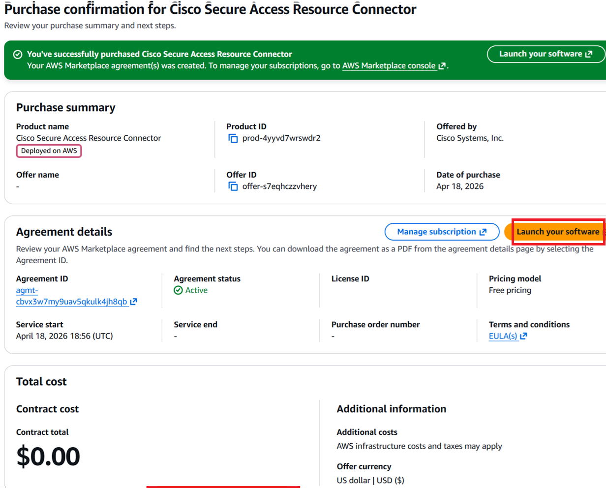
⑧Go to Launch your software.
⑨Select Asia Pacific (Tokyo) for Region and go to Launch from EC2.
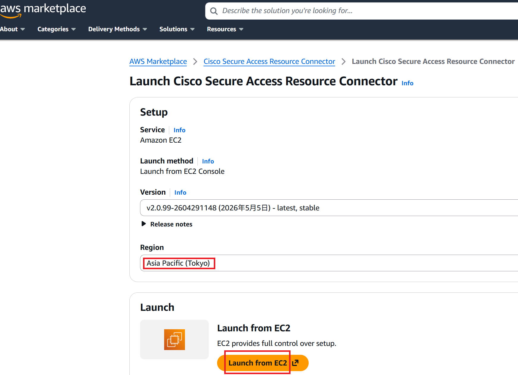
⑩Enter any instance name. This time I used AWS-Tokyo-RC1.
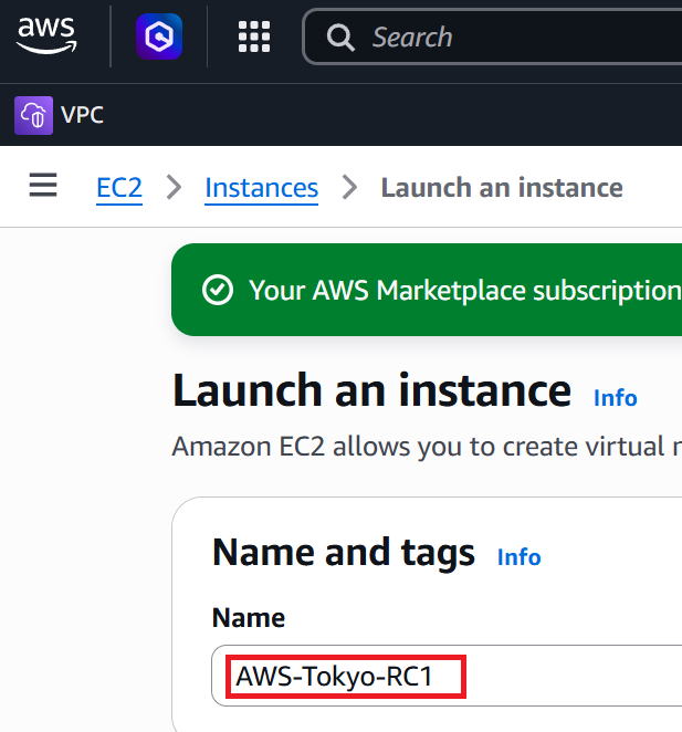
⑪Scroll down the screen. The Instance type is c5.xlarge, which is selected by default.
Select any key pair you like. Click edit on the right side of Network settings.
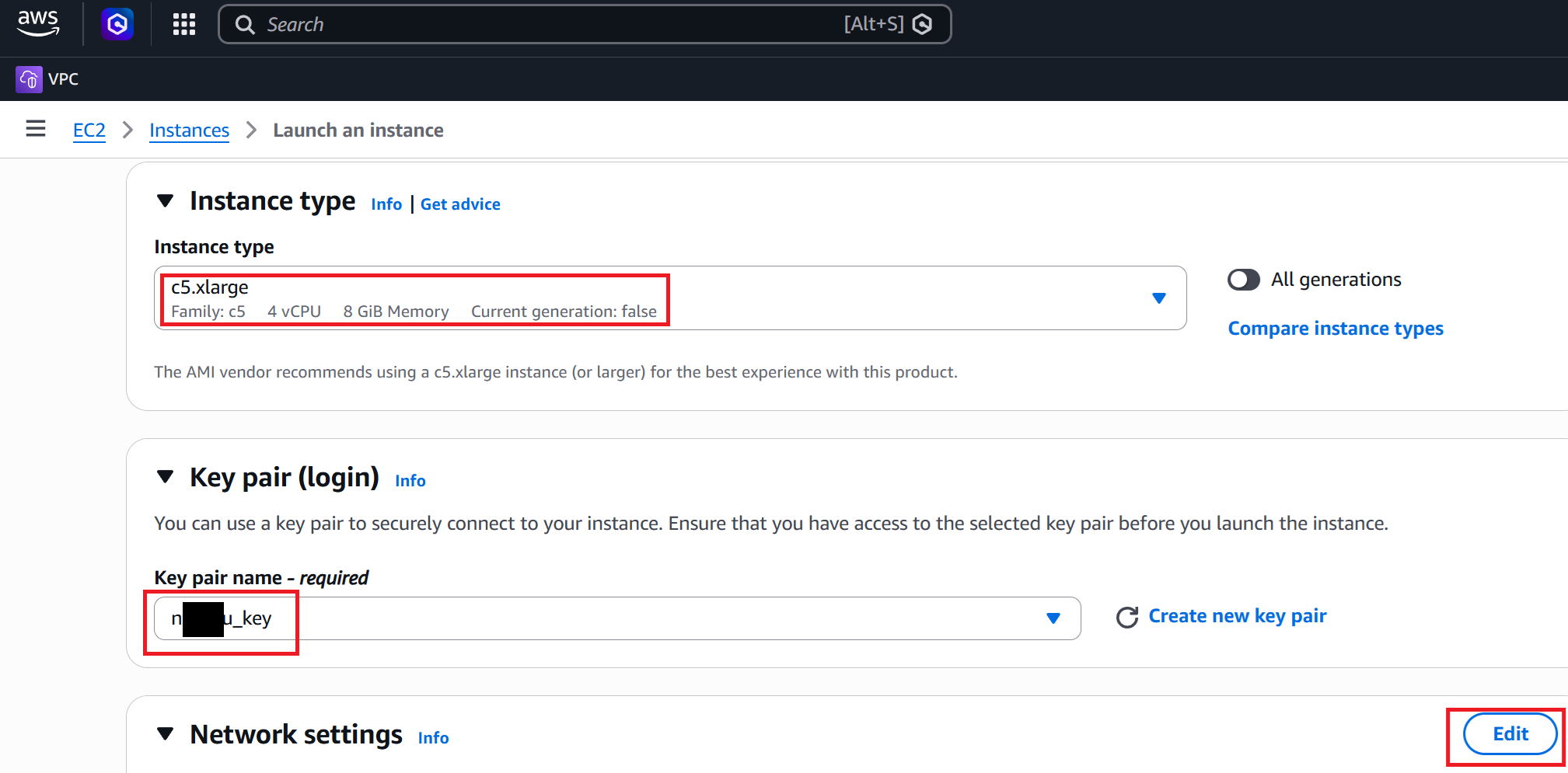
⑫Select the VPC and Subnet where RC1 will be built. Also set Auto-assign public to Enable so it can access the internet.
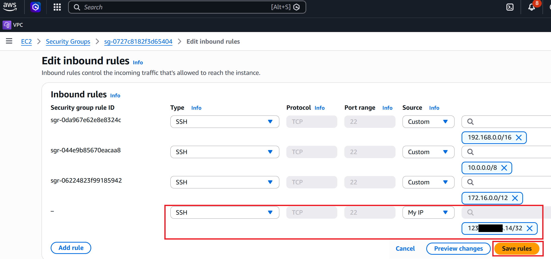
The security group applied by default only allows SSH from private IPs (10.0.0.0/8, 172.16.0.0/12, 192.168.0.0/16).
Later on, we'll edit the security group so we can SSH in over the internet from our home's global IP.
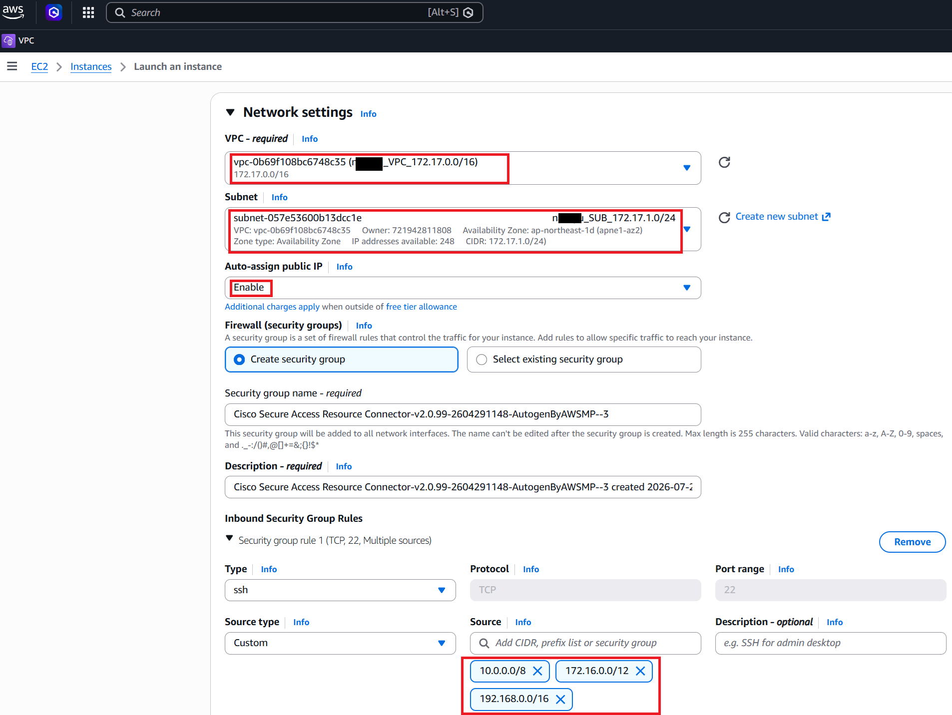
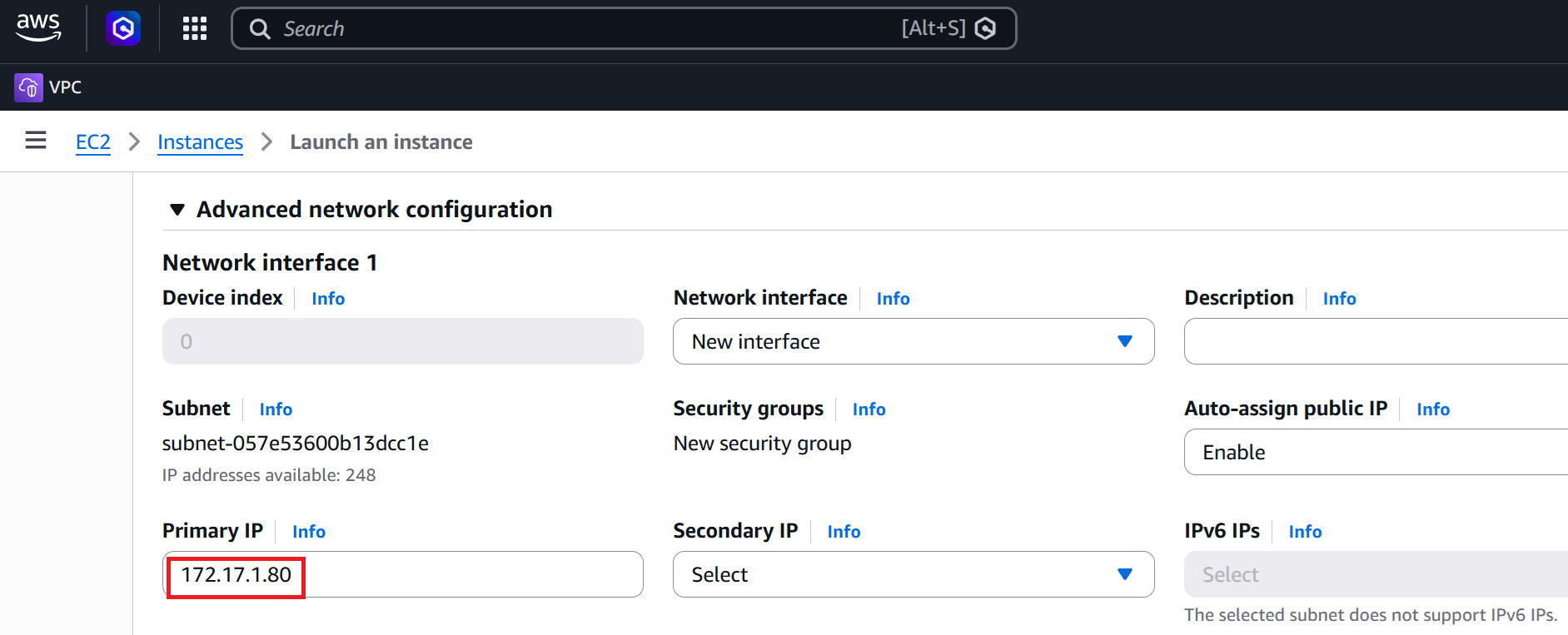
⑬Open Advanced network configuration and set any IP you like for Primary IP. This time I used 172.17.1.80.
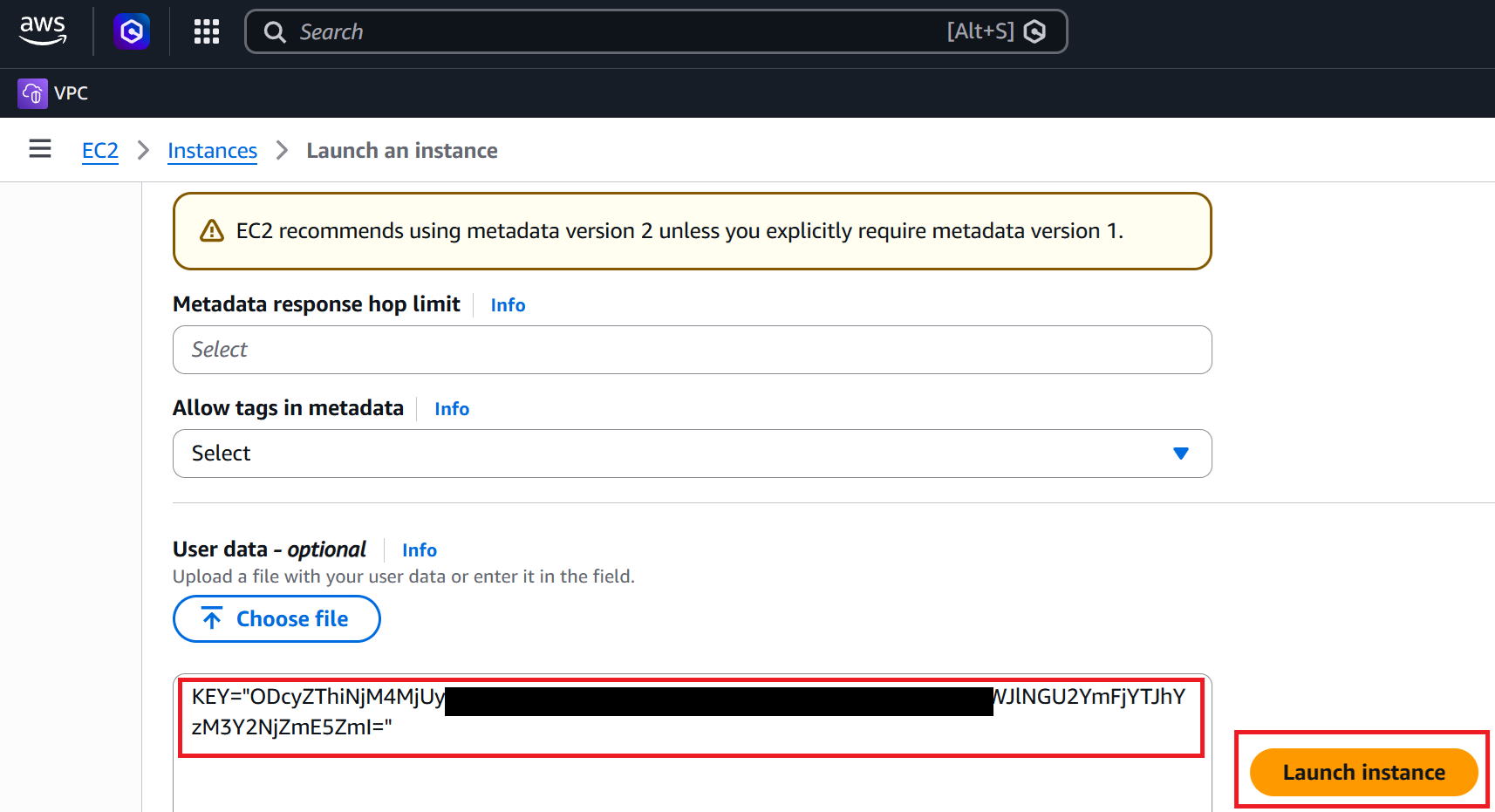
⑭If you scroll all the way to the bottom of the screen, a field called User data - optional appears.
Enter KEY="xxxxxxxxxxxx" here.
For xxx, paste the Provisioning key you noted down in step ⑤.
Then proceed to Launch instance to start the VM. Once it starts, the RC will automatically attempt to connect to Secure Access.
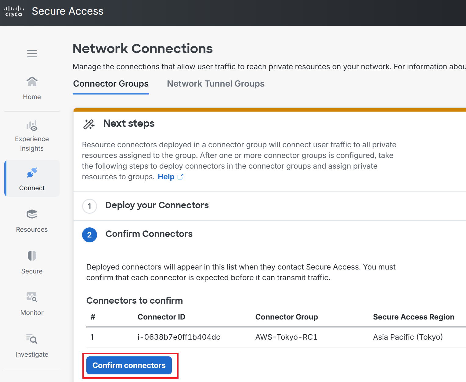
⑮Back on the Secure Access screen, a button labeled Confirm Connectors appears—click it.
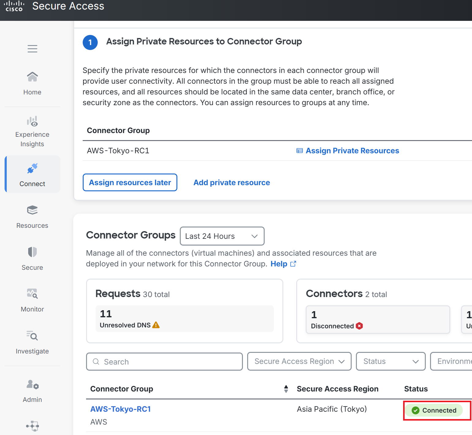
⑯As shown in the red box, the status successfully changed to Connected.
Trying to access the RC1 we built
|
Let's try making an administrative connection to the RC1 we built, shown in the red box. |
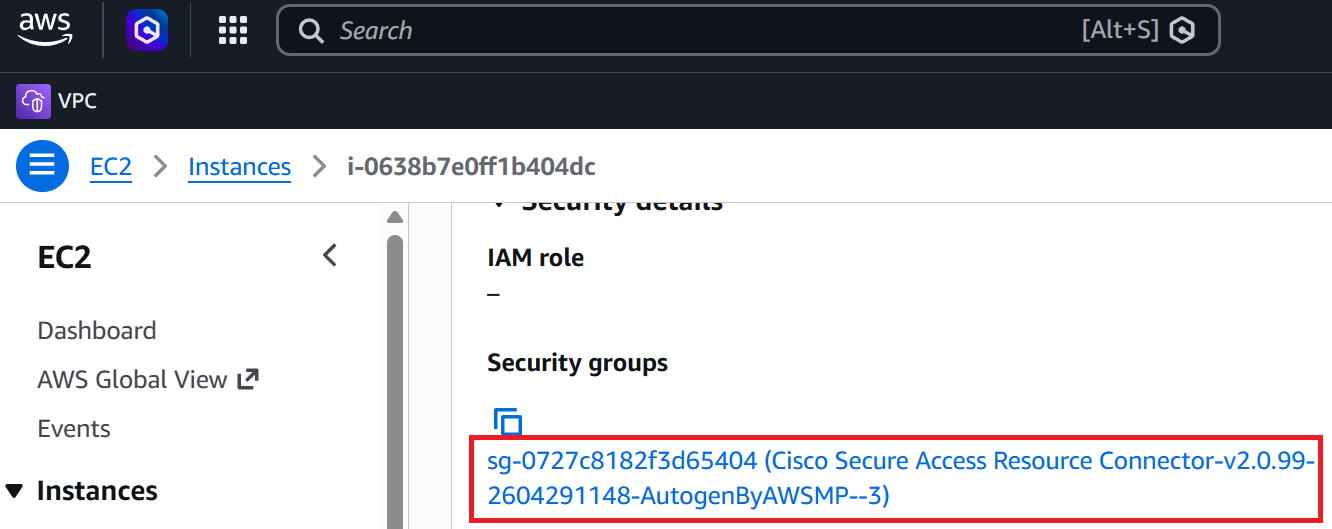
①Go to the area marked in red to edit the security group applied to RC1.
②Go to Edit Inbound rules.

③Add an allow rule with your home's global IP as the source address, as shown in the red box, so you can SSH in from home over the internet.
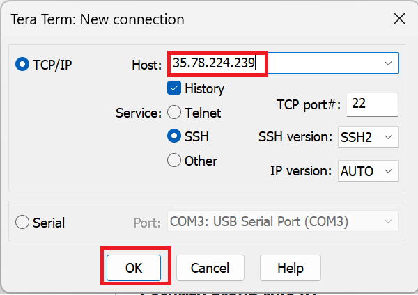
④Open TeraTerm, enter RC1's dynamic global IP, and click OK.
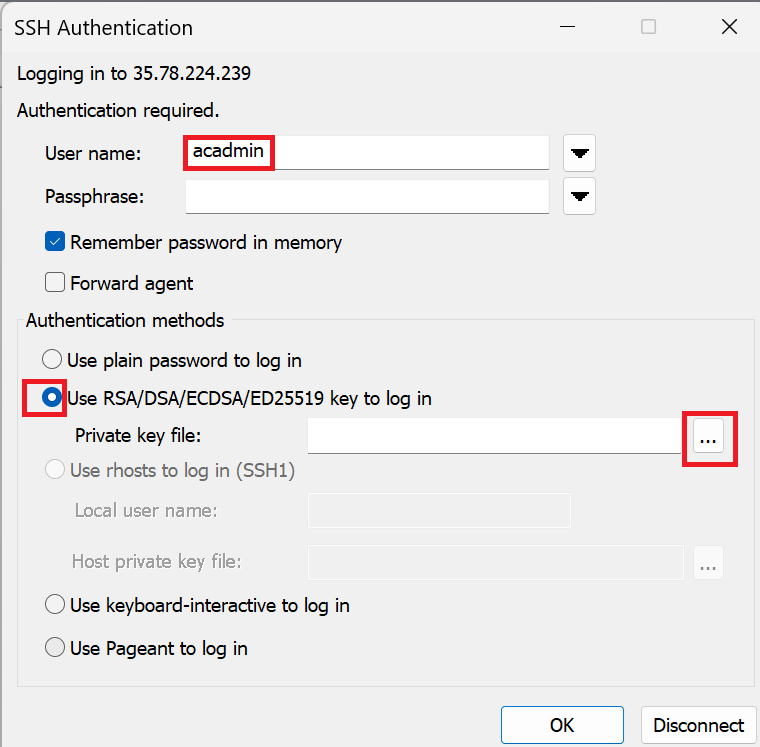
⑤Enter acadmin for User name.
For Authentication methods, select Use RSA~, click the red box on the right, select the key you chose when building the VM, and click OK.
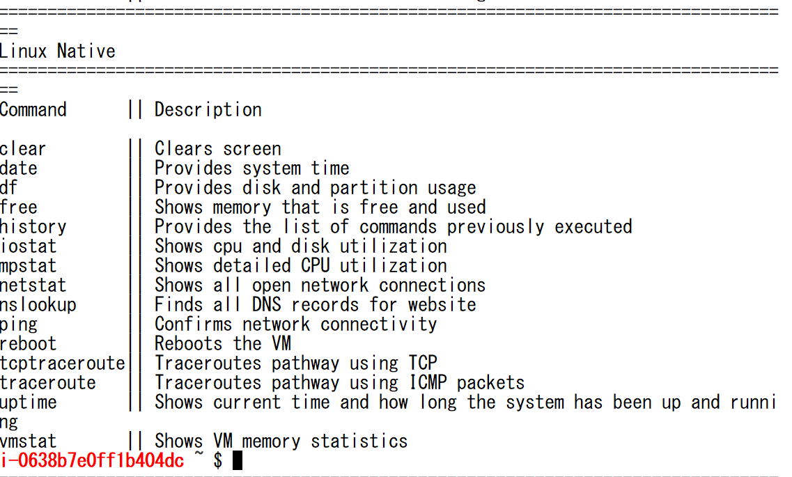
⑥Successfully logged in. The RC is Linux-based.
|
After walking through all of that, honestly there wasn't really anything you actually needed to do via administrative access to the RC... |
|
Wait, so that was all pointless? |
|
...Yes. So it's totally fine to skip this step! |
Configuring Private Resources
|
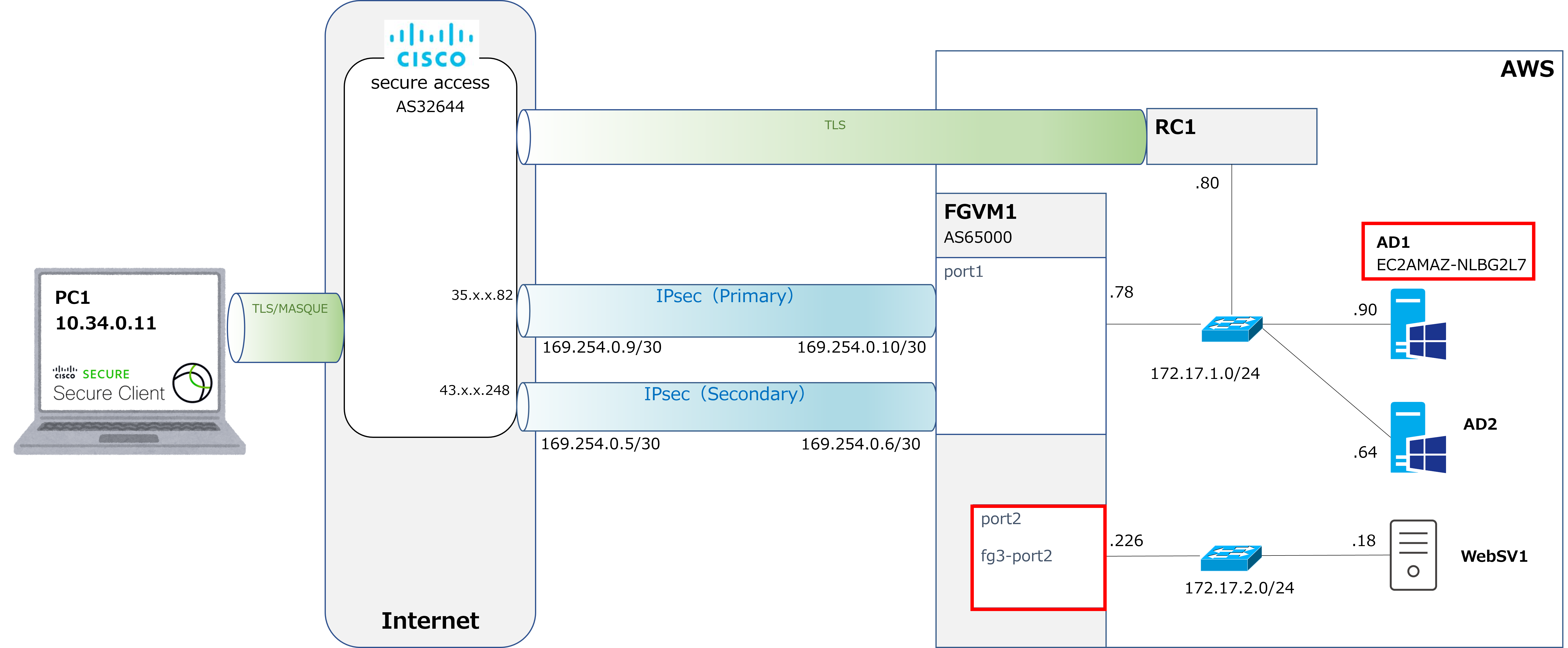
Next, we'll configure the Private Resources. This time we'll try RDP to AD1 and HTTPS to the FortiVM's port2. |
|
Got it. This is the same thing we did with VPNaaS too, right? The one where you specify the destinations that remote access devices can reach. |
|
That's right. Let's start with AD1. |
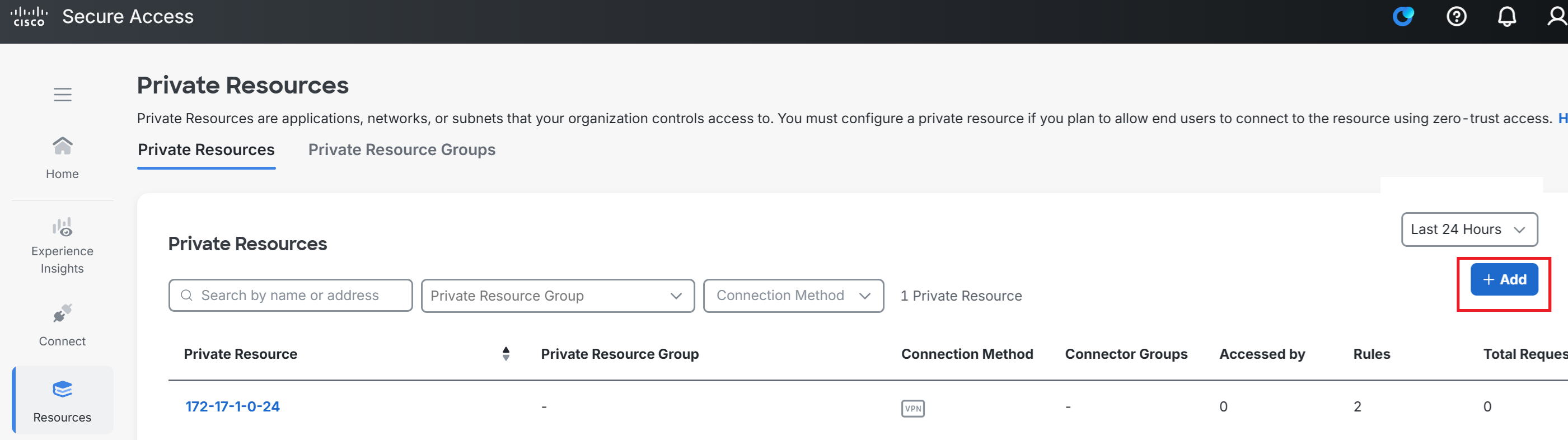
①Go to Resource → Private Resources → +Add.
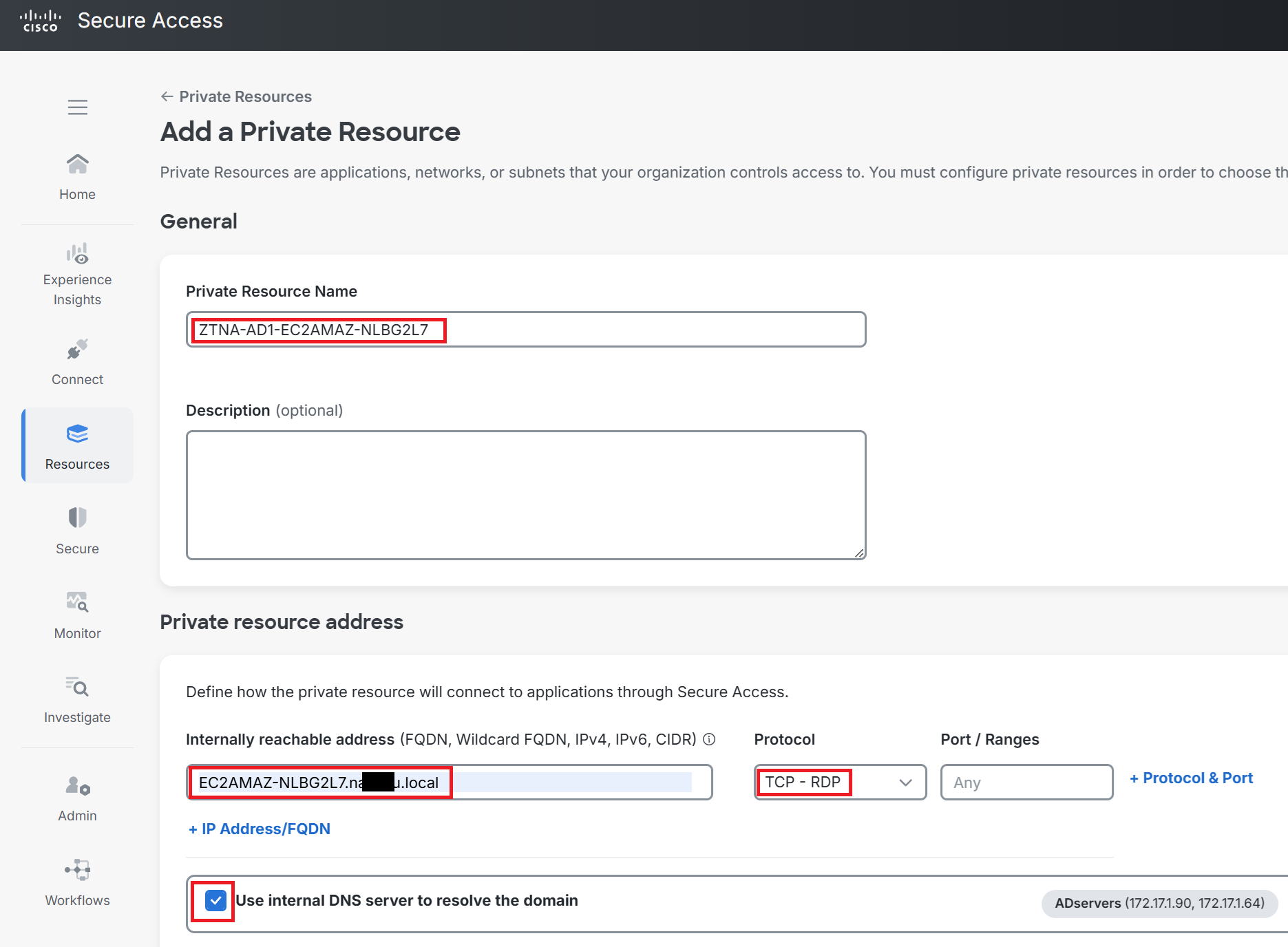
②Enter any name you like for Private Resource Name. This time I used ZTNA-AD1-EC2AMAZ-NLBG2L7.
For Internally reachable address, enter EC2AMAZ-NLBG2L7.naxxxx.local, which is AD1's hostname plus domain name.
Select RDP for Protocol.
Check Use internal DNS server to resolve the domain, and select the IP address of AD1, which is acting as the internal DNS server.
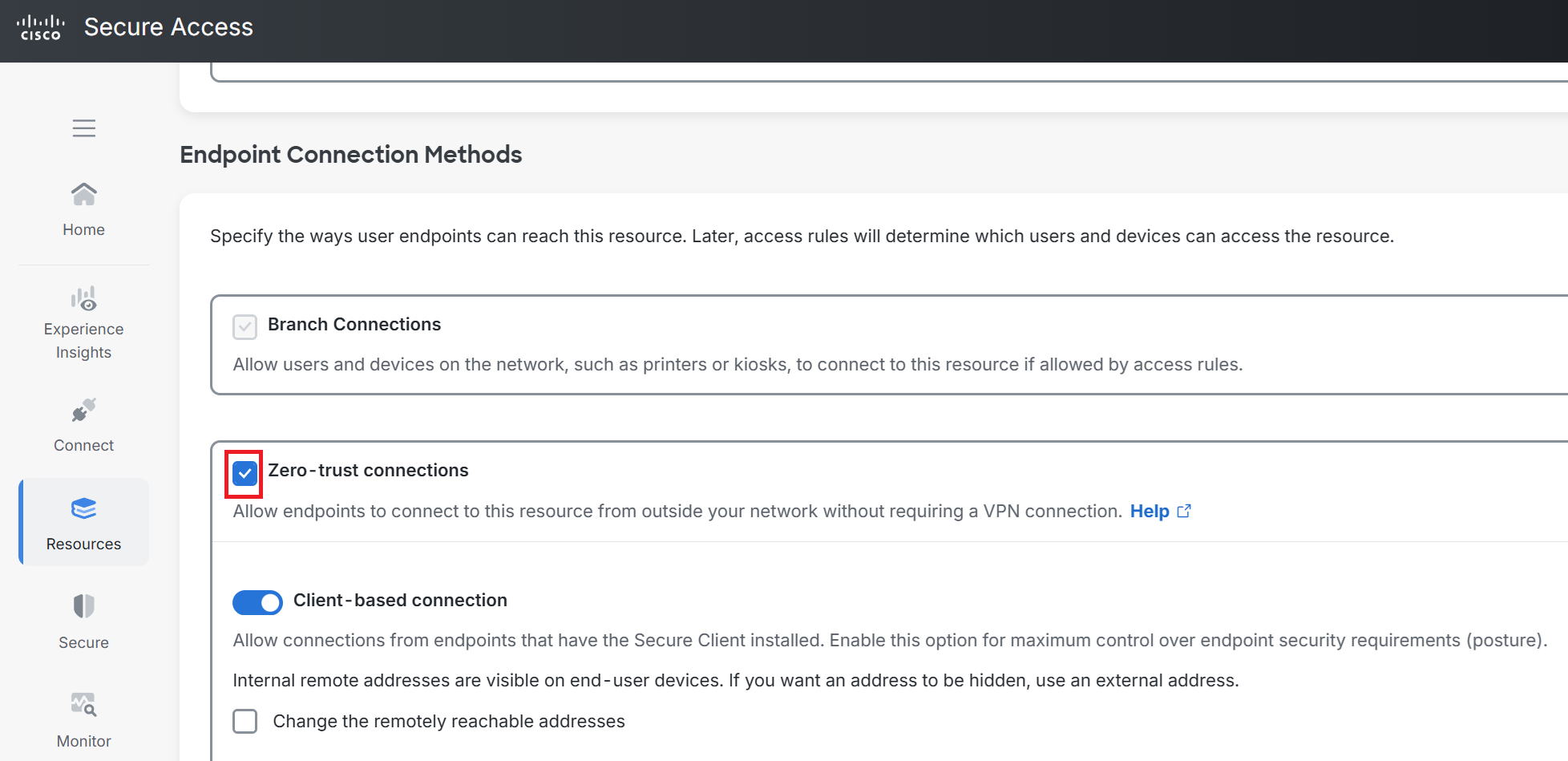
③Scroll down and check Zero-trust connections. Click Save at the bottom right of the screen.
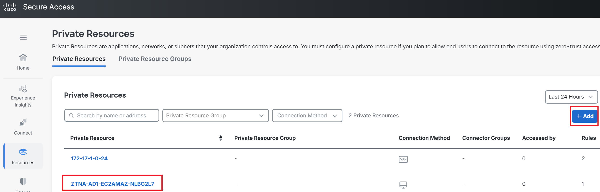
④As shown in the red box at the bottom left, ZTNA-AD1-EC2AMAZ-NLBG2L7 has been created and is now displayed.
To also make the FortiVM's port2 a ZTNA destination, go to +Add at the top right again.
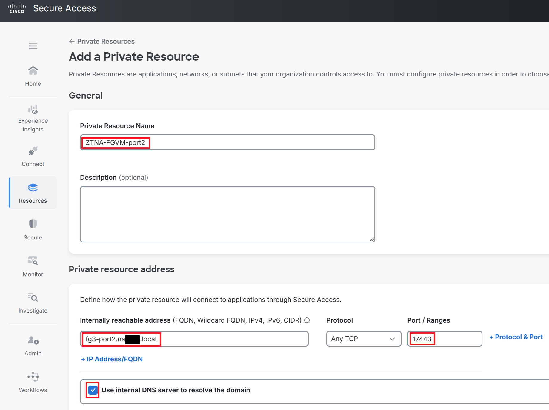
⑤Enter any name you like for Private Resource Name. This time I used ZTNA-FGVM-port2.
For Internally reachable address, I used fg3-port2.na■■■■.local, which resolves to 172.17.2.226 via the internal DNS server. The port number used for the management HTTPS connection to this FortiVM is a customized 17443 instead of the usual 443, so select Any TCP for Protocol and enter 17443 for the port number.
Check Use internal DNS server to resolve the domain here as well.
⑥Scroll down and check Zero-trust connections. Click Save at the bottom right of the screen.
SAML configuration with Entra ID for ZTA enrollment
|
Next, we'll configure SAML for enrolling in ZTNA (referred to as ZTA within Cisco Secure Access). Just like when we connected VPNaaS, we'll set this up to authenticate via SAML federation with Entra ID. |
|
Wait, this is getting complicated. First of all, what is Enroll? |
|
This is the procedure needed the first time a device connects to Secure Access via ZTA. We'll actually walk through it later, but in this case, we'll set things up so that enrollment is completed once Entra ID authentication succeeds. To do that, we need to configure SAML federation with Entra ID. |
|
Huh? Didn't we already set up SAML federation with Entra ID back when we created the VPN profile for the VPNaaS connection in Scenario 1? |
|
That's right, it is. This SAML federation setup has to be done separately for VPNaaS and for ZTA. It confused me too, at first. |
|
Ah, I see. That is confusing... |
|
Well, it's just how the spec works, so there's not much we can do about it. Anyway, let's go through the steps. |
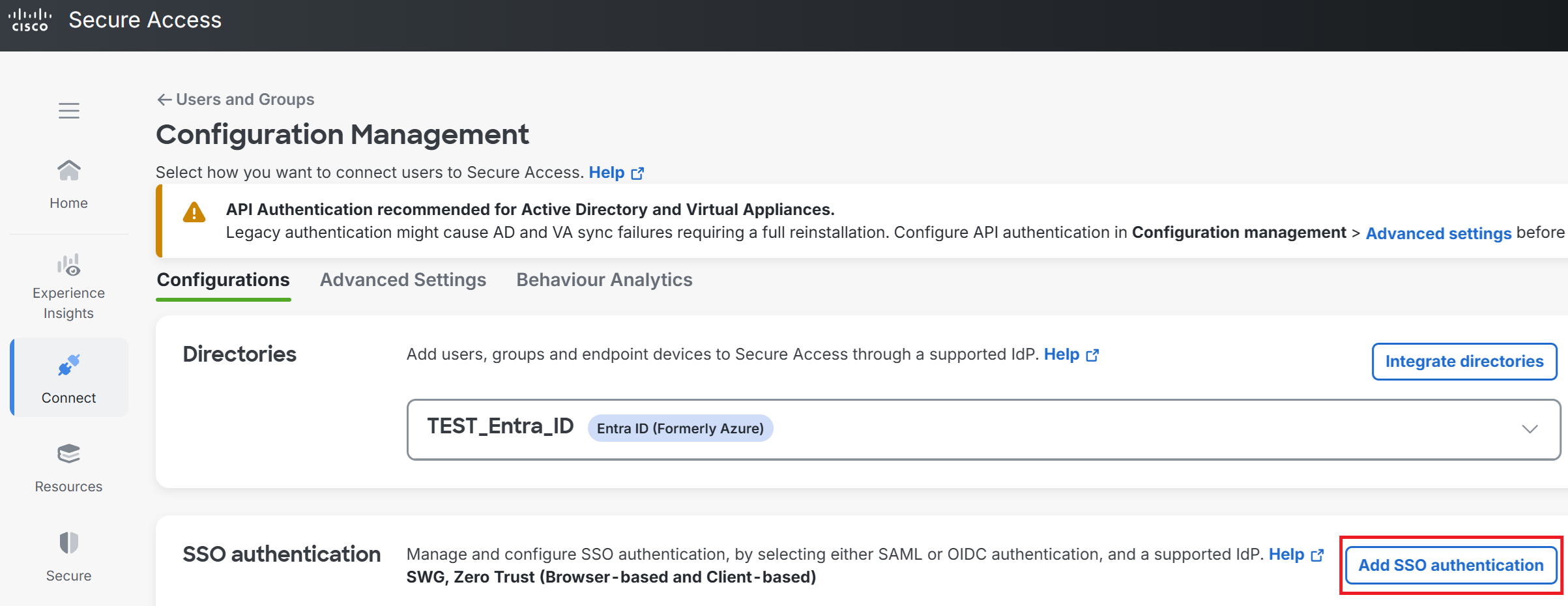
①Go to Connect → Users, Groups, and Endpoint Devices → Configuration management.
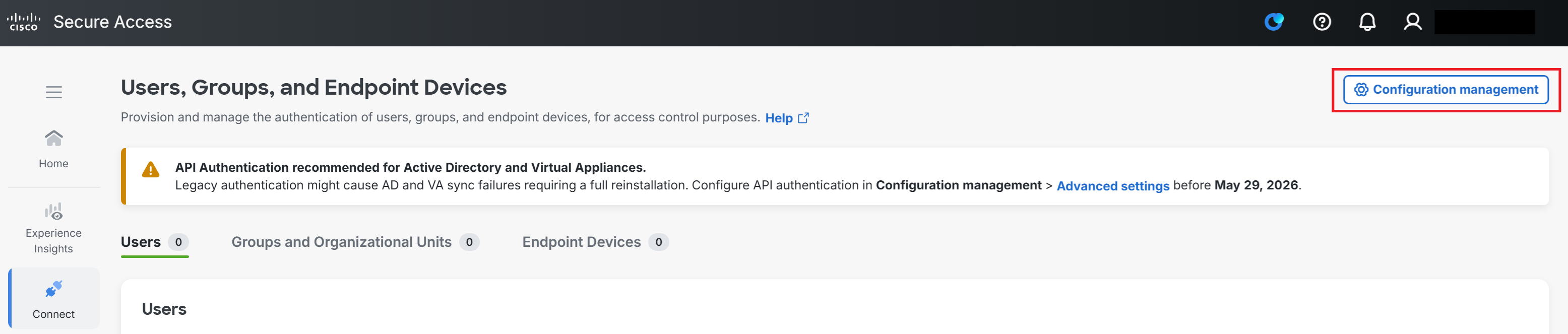
②Go to Add SSO authentication.
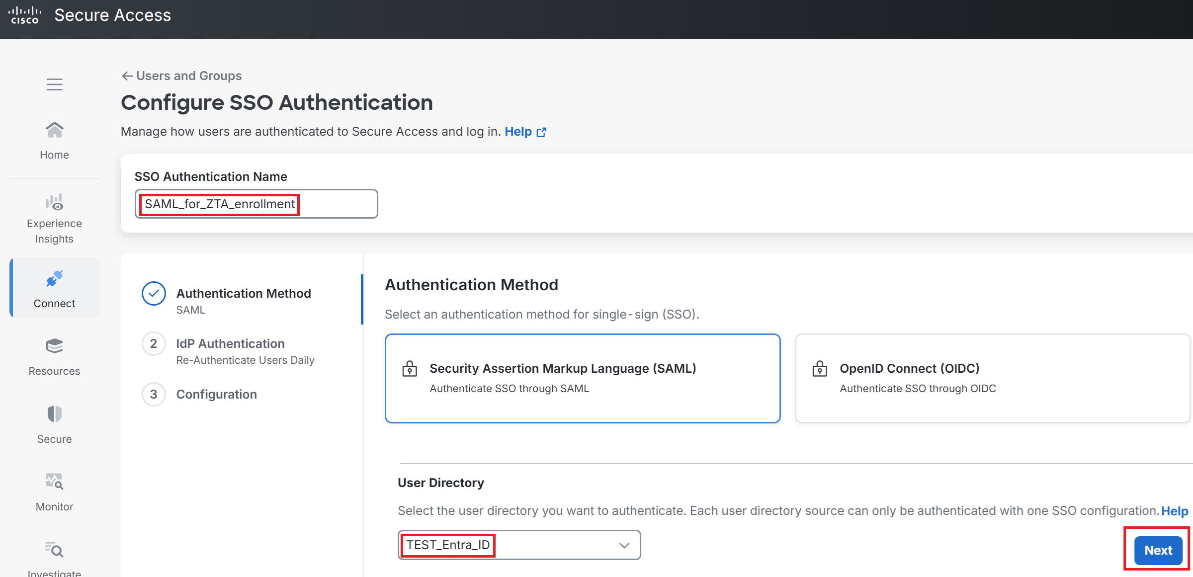
③Enter any name you like for SSO Authentication Name. This time I used SAML_for_ZTA_enrollment.
For User Directory, select TEST_Entra_ID, the one from when we configured SCIM, then click Next.
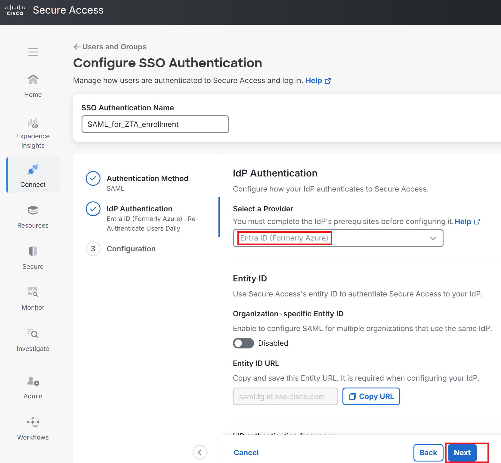
④Select Entra ID from Select a Provider. Leave everything else as-is and click Next.
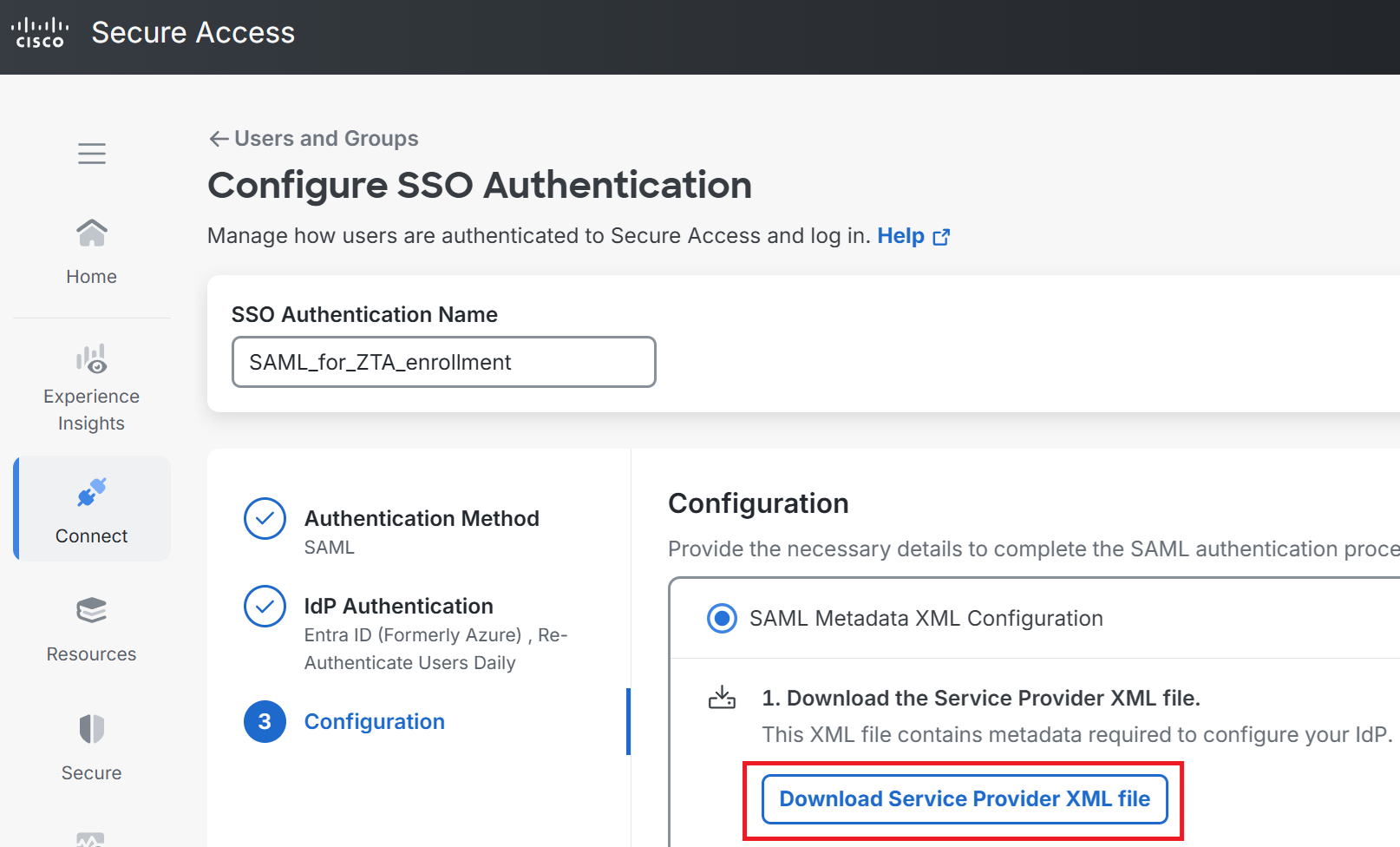
⑤Click Download Service Provider XML file.
An XML file named Cisco_SSE_SP_Metadata.xml is downloaded.
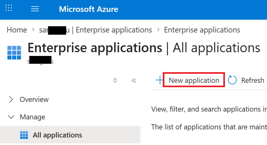
⑥Switch to the Entra ID screen and go to New application from the Enterprise applications page.
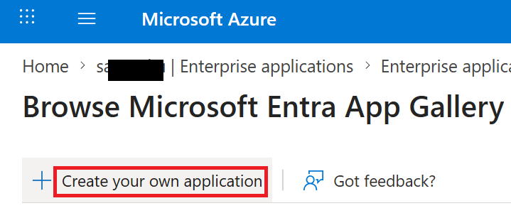
⑦Go to Create your own application.
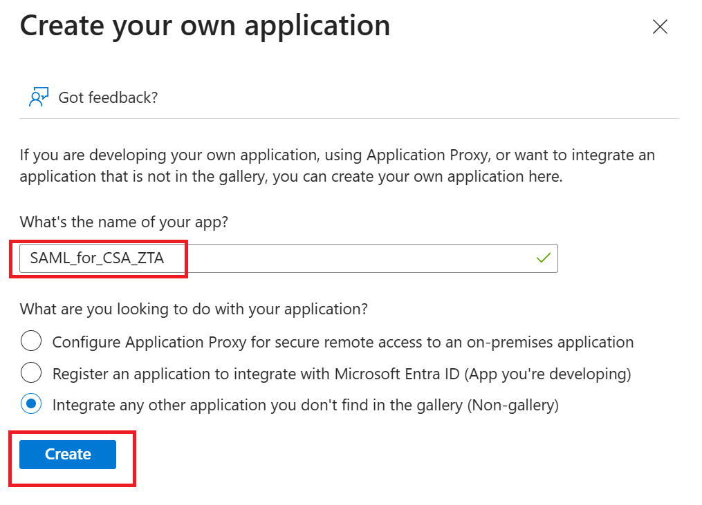
⑧Enter any app name you like. This time I used SAML_for_CSA_ZTA. Then click Create at the bottom left.
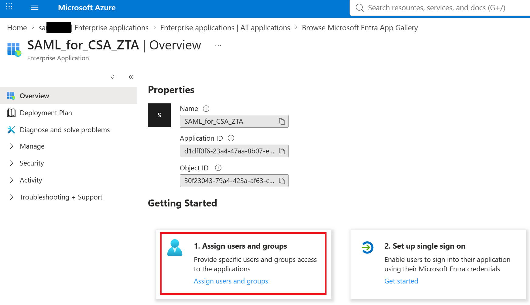
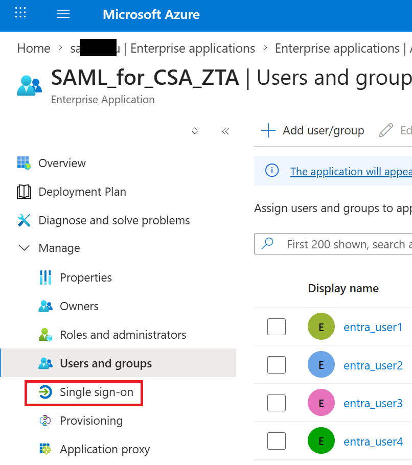
⑨Go to Assign users and groups.
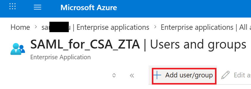
⑩Go to Add user/group.
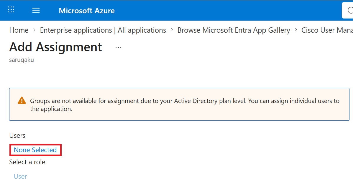
⑪To link this app to users, click None Selected.
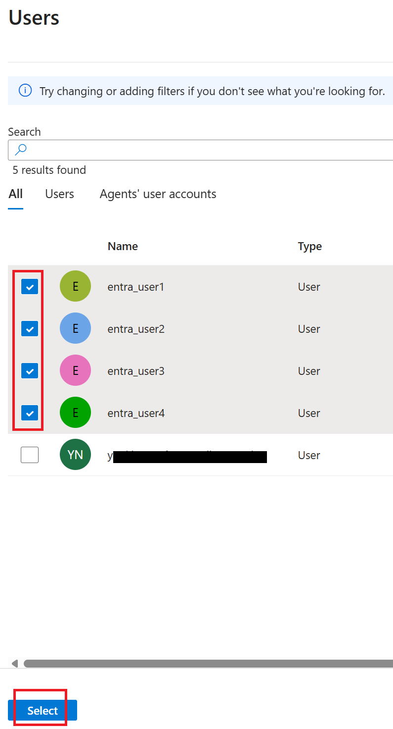
⑫The screen below appears on the right side of the display. This time I selected entra_user1 through entra_user4 and clicked select at the bottom left.
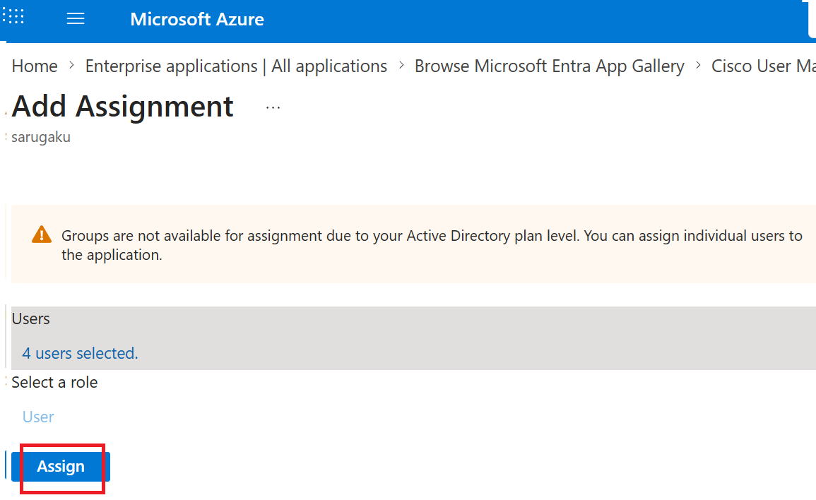
⑬Go to Assign.
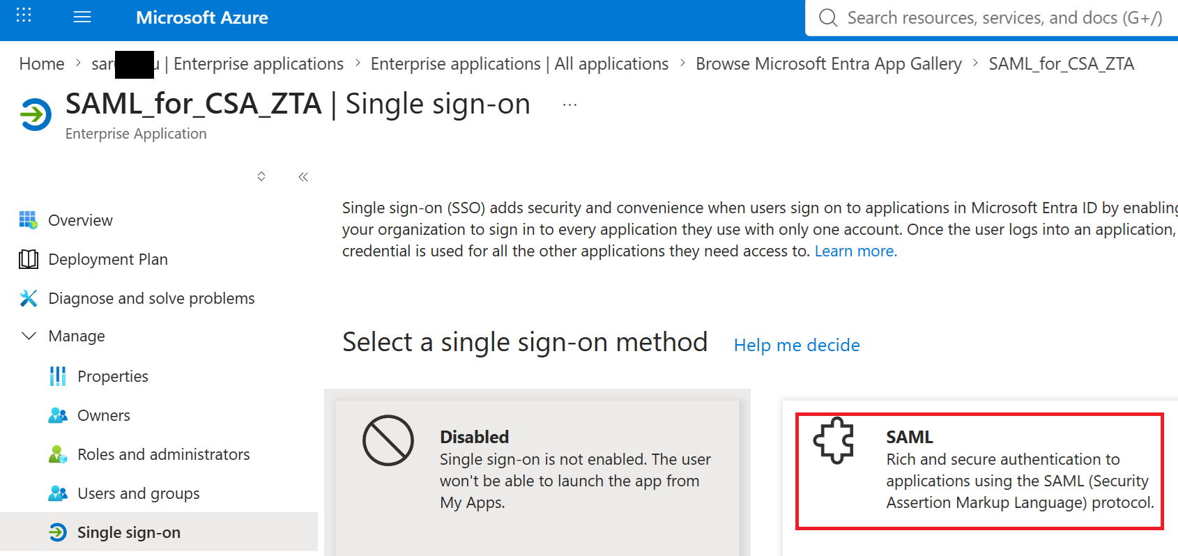
⑭Go to Single sign-on.
⑮Go to SAML.
⑯Click Upload metadata file.
On the screen that appears, select the Cisco_SSE_SP_Metadata.xml file you downloaded from Secure Access, and click Add.
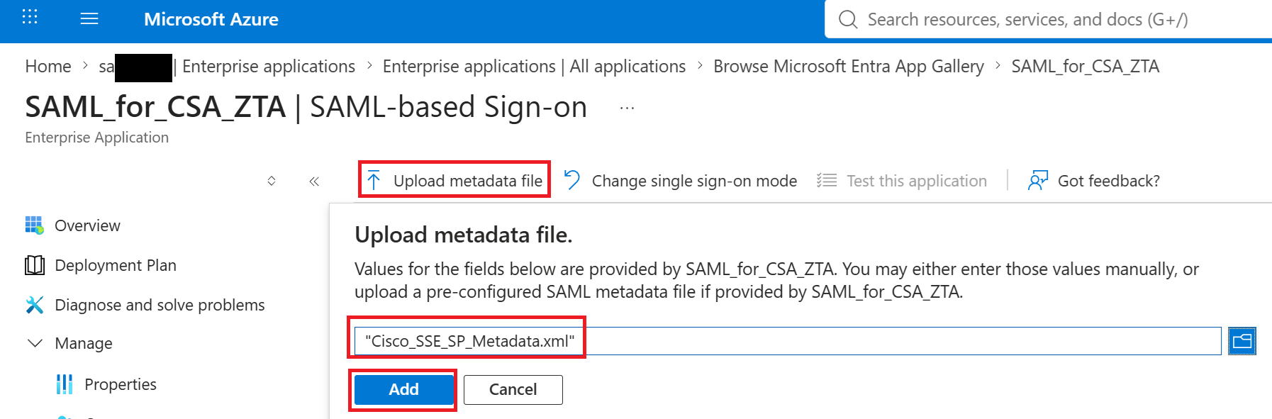
⑰A new panel appears at the top right of the screen, so click Save.

⑱Click Download in the red box.
An XML file named SAML_for_CSA_ZTA.xml is downloaded.
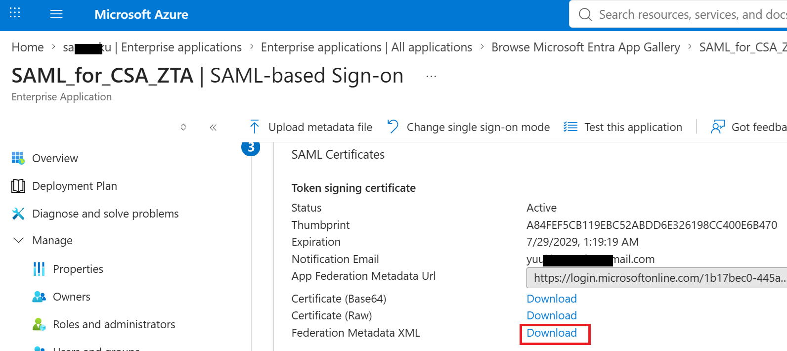
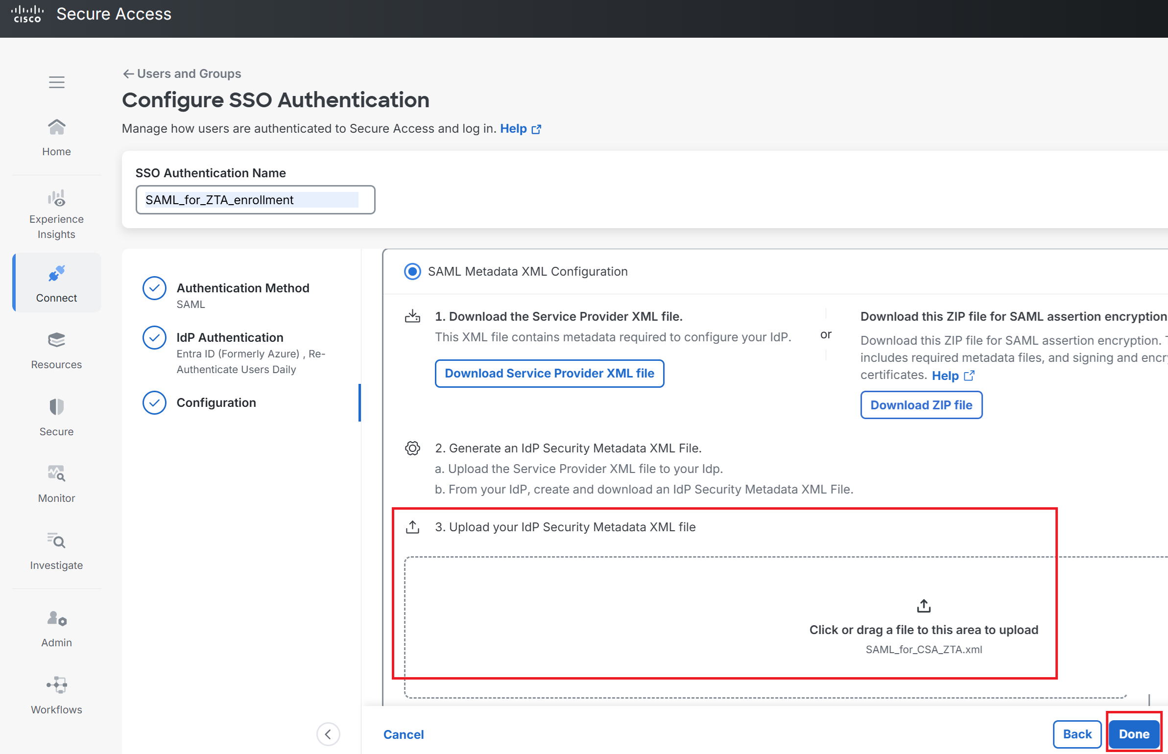
⑲Go back to the Secure Access screen and, in the area marked in red, upload the XML file you just downloaded from Entra ID.
Click Done at the bottom right.
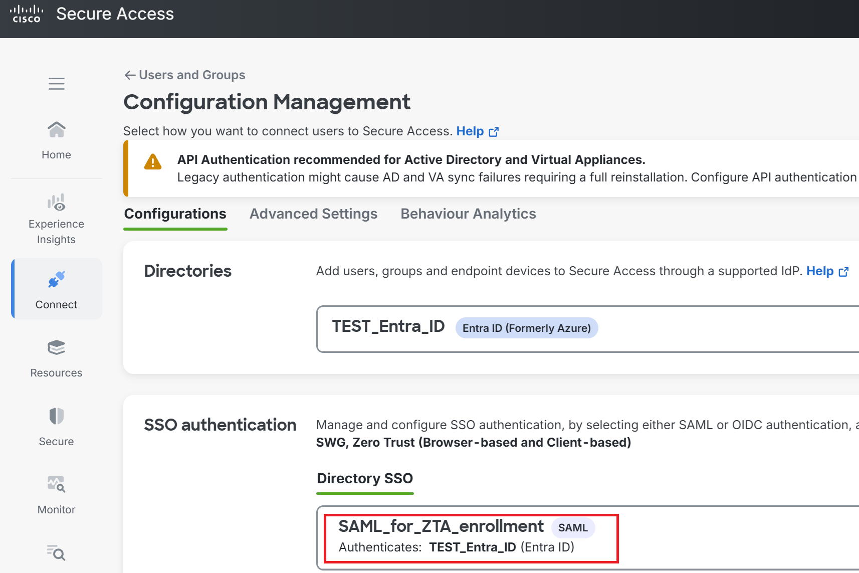
⑳As shown in the red box, it was successfully added.
Configuring the Access policy
|
Next, just as we did with VPNaaS, we'll configure the Access policy that allows remote access devices to reach Private Resources via ZTA. Let's start with the policy that has ZTA communicate with AD1 on the client's behalf, as shown by the red arrow in the diagram above. |
|
This is the same kind of thing as a Firewall policy on Fortigate, or a security policy on Palo Alto, right? |
|
That's right. |
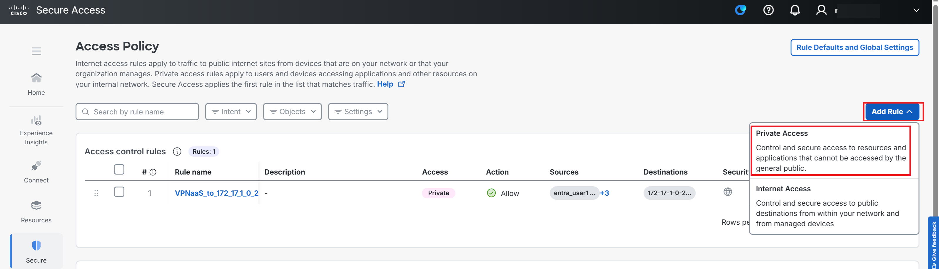
①Go to Secure → Access Policy → Add Rule → Private Access.
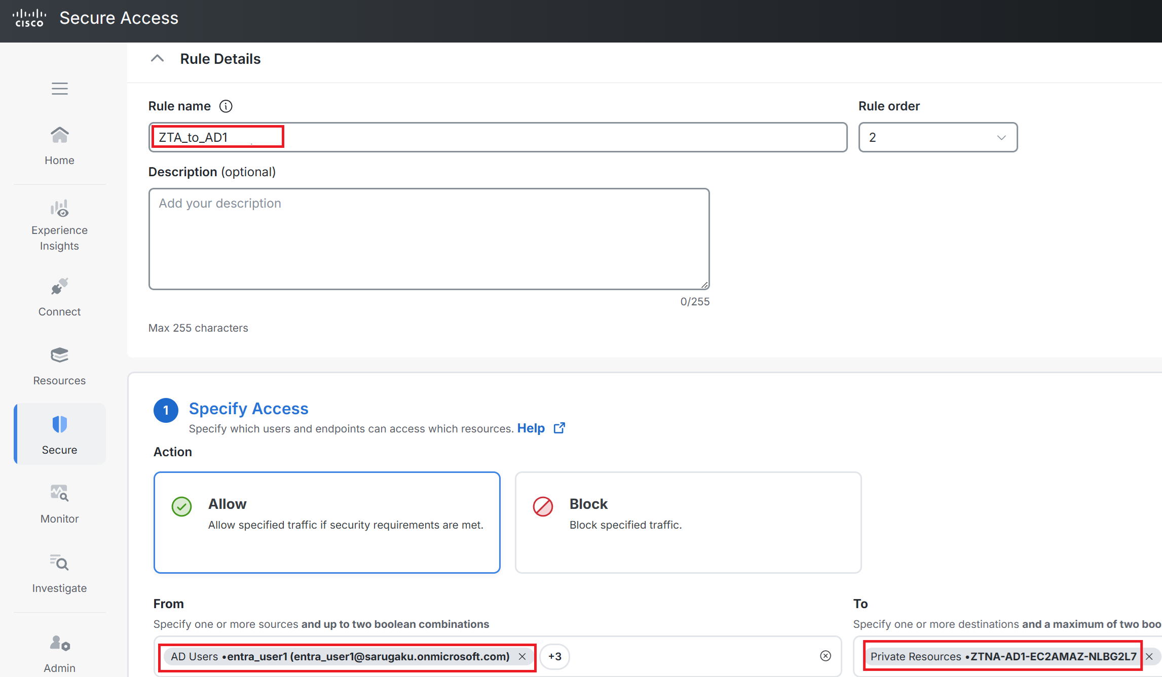
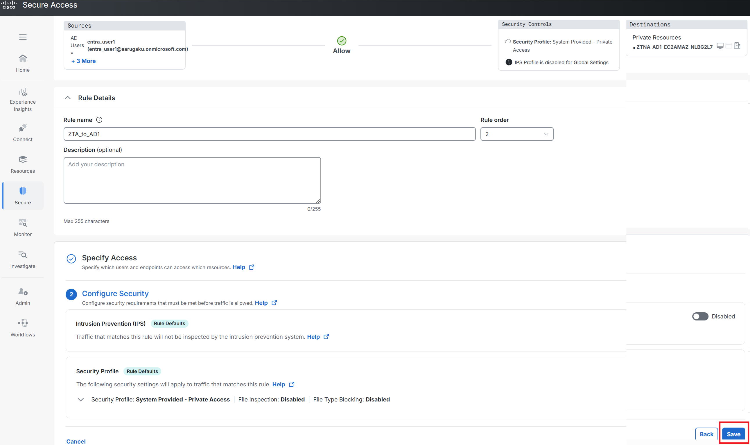
②Enter any name you like for Rule name. This time I used ZTA_to_AD1.
For From, select the four users imported from Entra ID (entra_user1 through entra_user4).
For To, select ZTNA-AD1-EC2AMAZ-NLBG2L7, which we created under Private Resource.
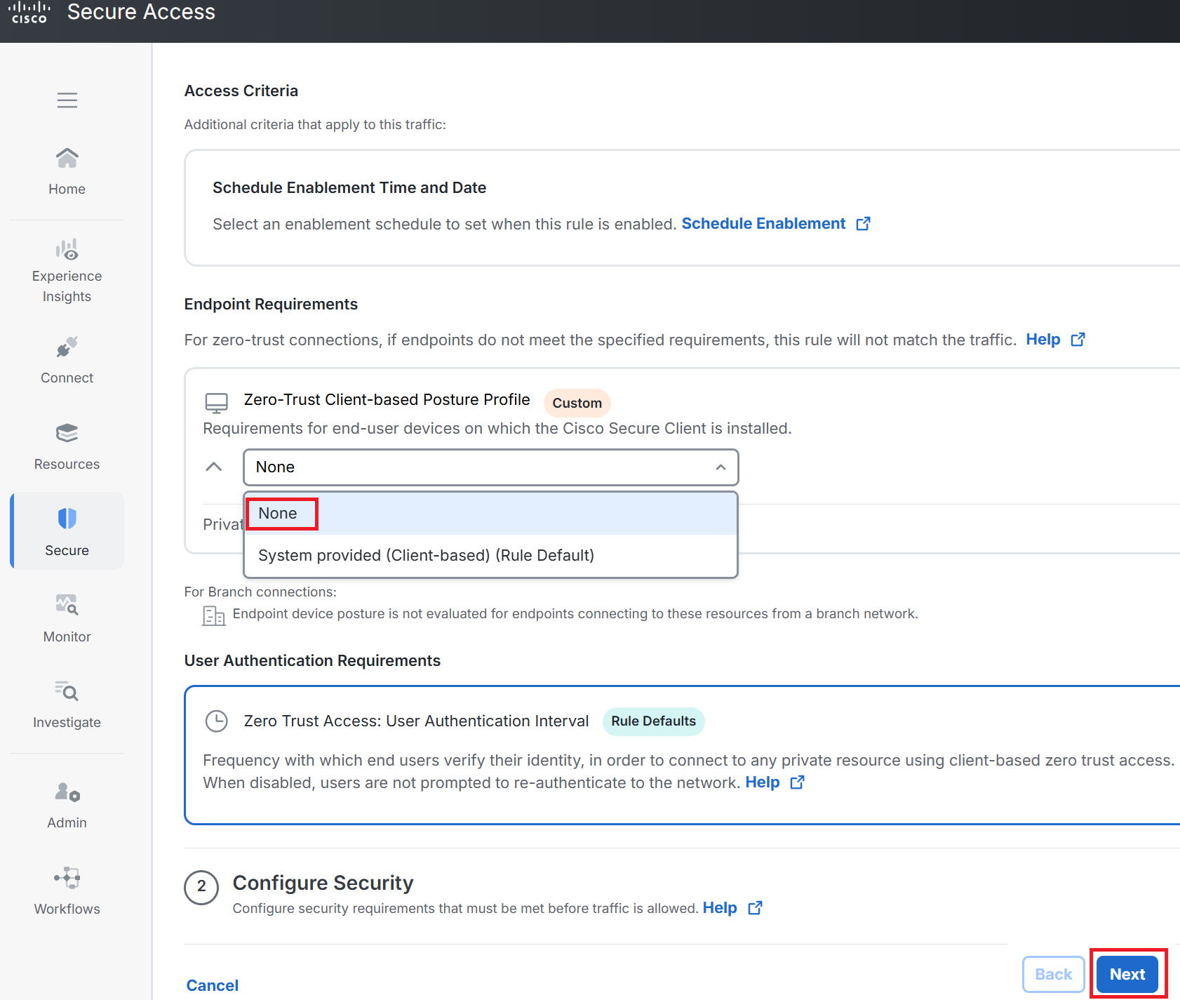
③Select None for Zero-Trust Client-based Posture Profile.
Posture is a feature that checks things like whether the device's OS version is acceptable, or whether antivirus software is running. With the default profile, the check fails if the device's disk isn't encrypted. Since the test PC isn't encrypted, it would fail this check, so we set the applied profile to None so posture checks are excluded. Strictly speaking you shouldn't set it to None, but this is just for testing.
Then click Next at the bottom right.
④Click Save.
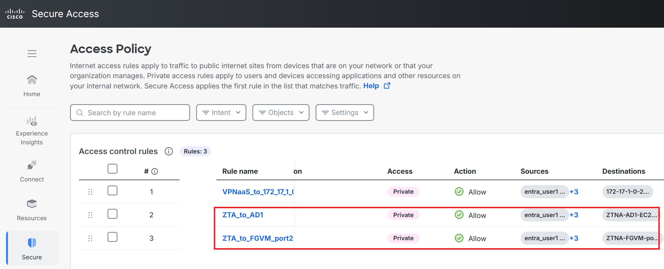
⑤Following the same steps, also create ZTA_to_FGVM_port2, the policy that allows ZTA access to the FGVM's Port2.
Installing the ZTA module on the test PC
|
Back in Scenario 1, Configuring VPNaaS for Remote Access, we installed the VPN module of Secure Client. This time, in addition to that, we'll install the ZTA module, cisco-secure-client-win-5.1.18.5828-zta-predeploy-k9.msi Let's go through those steps. |
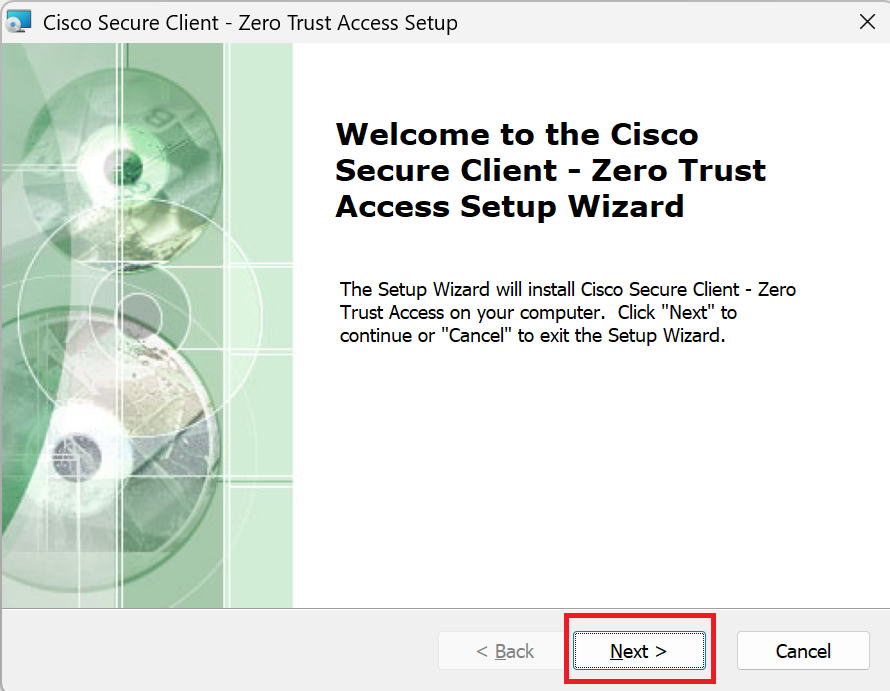
①Open the installer (cisco-secure-client-win-5.1.18.5828-zta-predeploy-k9.msi) and the wizard will appear—click Next.
②Check accept and click Next.
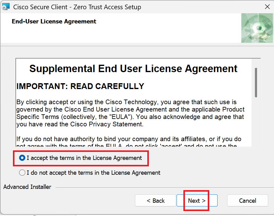
③Go to Install.
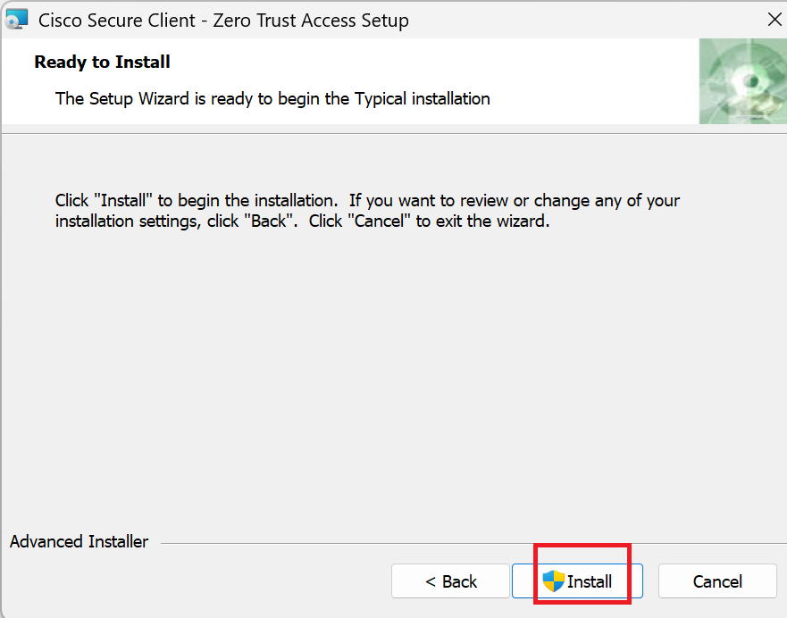
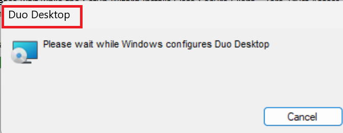
④An app called Duo Desktop is installed at the same time.
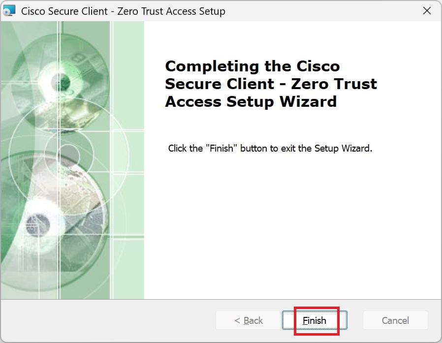
⑤Click Finish.
|
What's Duo Desktop actually installed for? |
|
Apparently it's for the posture feature. The posture feature, which checks each time whether the device is legitimate, is really at the heart of ZTNA. I think it's fine to think of this as the app that makes that possible. |
|
I see. |
Enrolling in ZTA
|
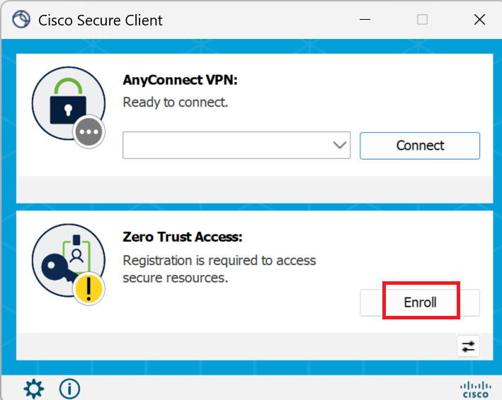
Once the ZTA module is installed, we'll perform enrollment in ZTA. This is a registration step that's only needed the first time. As you can see in the diagram below, there's a message asking you to register, saying: Registration is required to access secure resoruces |
①Go to Enroll.
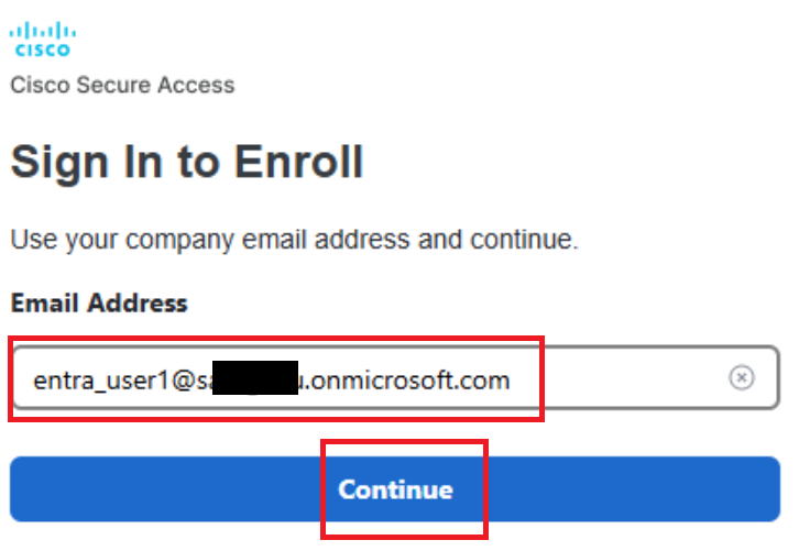
②Enter your Entra ID account and click Continue.
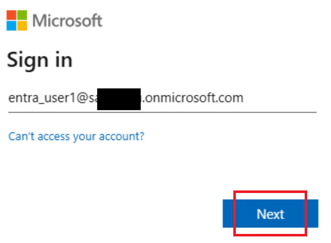
③When the Microsoft login screen appears, enter your Entra ID account again and click Next.
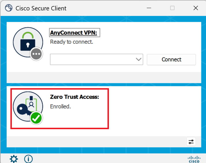
④Enter your password, and once authentication succeeds, it changes to Enrolled as shown below.
|
It shows Enrolled now. |
|
That's right. Now let's verify it's working. |
Verifying operation
|
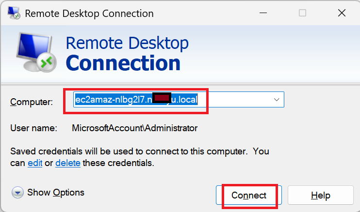
First, we're making an RDP connection from PC1 to AD1 (ec2amaz-nlbg2l7.nxxxxu.local) via ZTNA. |
Enter AD1's FQDN and click Connect. The connection succeeded.
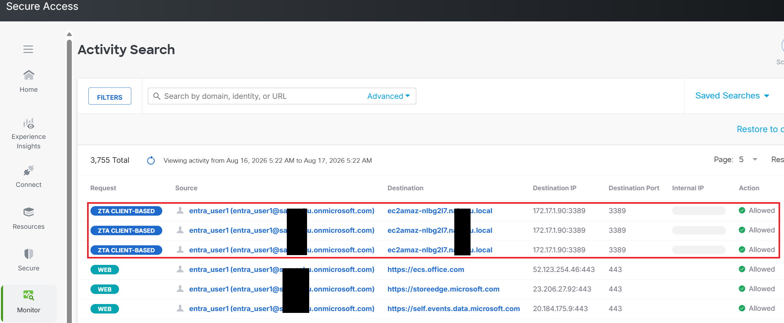
Looking at the Activity Search log in Secure Access, as shown in the red box, the RDP communication to port 3389 succeeded.
This is the Wireshark log on AD1, our internal DNS server. It's filtered to show only DNS traffic (port 53 communication).
As shown in the red box, a query is sent from 172.17.1.80 (the RC's IP address) to 172.17.1.90 (the internal DNS server's IP address), and a reply is sent back. In other words, this shows that the RC is handling DNS communication on PC1's behalf as well.

|
It worked. |
|
That's right. This one was really long again, but thanks for reading. |